Nissan Juke Service and Repair Manual : ABS actuator and electric unit (control unit)
Exploded View
LHD
MR16DDT (2WD), HR16DE
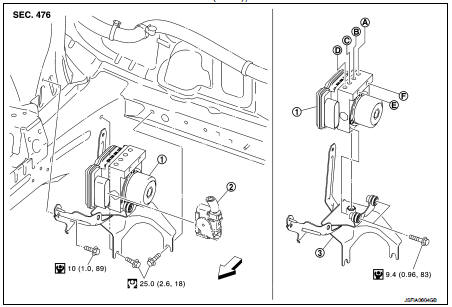
1. ABS actuator and electric unit (control
unit)
2. ABS actuator and electric unit (control
unit) harness connector
3. Bracket
A. To front LH caliper
B. To rear RH caliper
C. To rear LH caliper
D. To front RH caliper
E. To master cylinder secondary side
F. To master cylinder primary side
 : Vehicle front
 : N·m (kg-m, ft-lb)
 : N·m (kg-m, in-lb)
MR16DDT (4WD)
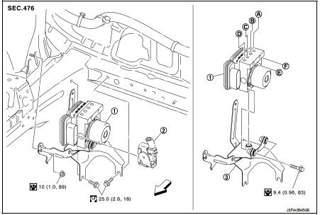
1. ABS actuator and electric unit (control
unit)
2. ABS actuator and electric unit (control
unit) harness connector
3. Bracket
A. To front LH caliper
B. To rear RH caliper
C. To rear LH caliper
D. To front RH caliper
E. To master cylinder secondary side
F. To master cylinder primary side
: Vehicle front
: N·m (kg-m, ft-lb)
: N·m (kg-m, in-lb)
K9K
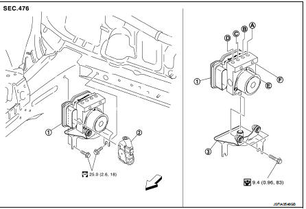
1. ABS actuator and electric unit (control
unit)
2. ABS actuator and electric unit (control
unit) harness connector
3. Bracket
A. To front LH caliper
B. To rear RH caliper
C. To rear LH caliper
D. To front RH caliper
E. To master cylinder secondary side
F. To master cylinder primary side
: Vehicle front
: N·m (kg-m, ft-lb)
: N·m (kg-m, in-lb)
RHD
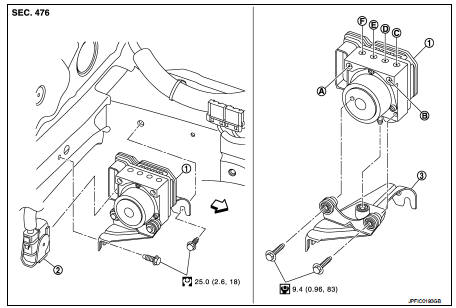
1. ABS actuator and electric unit (control
unit)
2. ABS actuator and electric unit (control
unit) harness connector
3. Bracket
A. To master cylinder secondary side
B. To master cylinder primary side
C. To front LH caliper
D. To rear RH caliper
E. To rear LH caliper
F. To front RH caliper
: Vehicle front
: N·m (kg-m, ft-lb)
: N·m (kg-m, in-lb)
Removal and Install
REMOVAL
1. Disconnect battery cable from negative terminal.
2. Drain brake fluid.
• LHD: Refer to BR-12, "Draining".
• RHD: Refer to BR-80, "Draining".
3. Remove air cleaner case and air duct. (RHD) Refer to EM-161, "Removal and Installation".
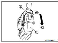
4. Disconnect ABS actuator and electric unit (control unit) harness connector (1), follow the procedure described below.
a. Push the pawl (A).
b. Move the lever (B) in the direction (C) until locked.
c. Disconnect ABS actuator and electric unit (control unit) harness connector.
5. Loosen flare nut of brake tube using a flare nut wrench, and then remove brake tube from ABS actuator and electric unit (control unit).
• LHD Refer to BR-24, "FRONT : Exploded View".
• RHD Refer to BR-91, "FRONT : Exploded View"
6. Remove ABS actuator and electric unit (control unit) and bracket.
CAUTION
:
• Never remove and never install ABS actuator and electric unit (control unit)
by holding harness
connector.
• Be careful not to drop ABS actuator and electric unit (control unit) and apply excessive impact to it.
7. Remove bracket and bushing from ABS actuator and electric unit (control unit).
INSTALLATION
Note the following, and install in the reverse order of removal.
• When replacing with a new ABS actuator and electric unit (control unit), never remove the protector of the brake tube mounting hole until right before the brake tube is installed.
• When installing brake tube, tighten to the specified torque using a flare nut torque wrench so that flare nut and brake tube are not damaged.
- LHD: Refer to BR-24, "FRONT : Exploded View".
- RHD: Refer to BR-91, "FRONT : Exploded View".
• Never remove and install ABS actuator and electric unit (control unit) by holding actuator harness.
• Bleed air from brake piping after installation.
- LHD: Refer to BR-13, "Bleeding Brake System".
- RHD: Refer to BR-81, "Bleeding Brake System".
• Never apply excessive impact to actuator, such as by dropping it.
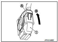
• After installing the ABS actuator and electric unit (control unit) harness connector (1), move the lever (A) in the direction (B) to secure the locking.
 Sensor rotor
Front sensor rotor : Removal and Installatio
REMOVAL
Replace wheel hub as an assembly when replacing because sensor rotor cannot
be disassembled.
• MR16DDT: Refer to FAX-11, "Removal and I ...
 Yaw rate/side/decel G sensor
Exploded View
1. Yaw rate/side/decel G sensor
2. Yaw rate/side/decel G sensor harness
connector
3. Bracket
: Vehicle front
: N·m (kg-m, in-lb)
Removal and Installation
REMOVAL
CAUTION:
Ne ...
Other materials:
B1185 lap Pre-tensioner LH
DTC Logic
DTC CONFIRMATION PROCEDURE
1.CHECK SELF-DIAGNOSTIC RESULT
With CONSULT-III
1. Turn ignition switch ON.
2. Perform “Self Diagnostic Result” mode of “AIR BAG” using CONSULT-III.
Without CONSULT-III
1. Turn ignition switch ON.
2. Check the air bag warning lamp status. Refer to SRC ...
Plug
Description
Replace the O-ring if oil leakage or exudes from the plug.
Exploded View
1. Plug
2. O-ring
3. O-ring
4. Plug
: Always replace after every
disassembly.
: N·m (kg-m, ft-lb)
: N·m (kg-m, in-lb)
: Genuine NISSAN CVT Fluid NS-2
Removal and Insta
NOTE:
Replace the O-rings if ...
The fuel gauge indicator does not operate
Description
Fuel gauge will not indicate from a certain position.
Diagnosis Procedure
1.CHECK COMBINATION METER OUTPUT SIGNAL
1. Connect CONSULT-III.
2. Select the “Data Monitor” for the “METER/M&A” and compare the “FUEL METER”
monitor value with the
fuel gauge reading on the combination ...
