Nissan Juke Service and Repair Manual : A/C switch
Component Function Check
1.CHECK A/C ON SIGNAL
 With CONSULT-III
1. Turn ignition switch ON.
2. Select “AIR CONDITIONER” of “BCM” using CONSULT-III.
3. Select “AIR COND SW” in “DATA MONITOR” mode, and check status under the following condition.
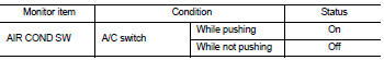
Is the inspection result normal? YES >> INSPECTION END
NO >> Refer to HAC-220, "Diagnosis Procedure".
Diagnosis Procedure
1.CHECK A/C SWITCH POWER SUPPLY
1. Turn ignition switch OFF.
2. Disconnect A/C control connector.
3. Turn ignition switch ON.
4. Check output waveform between A/C control harness connector and ground with using oscilloscope.
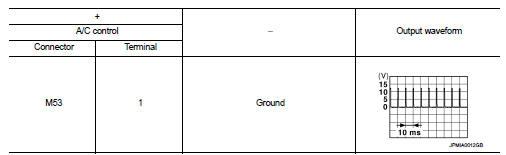
Is the inspection result normal? YES >> GO TO 2.
NO >> GO TO 3.
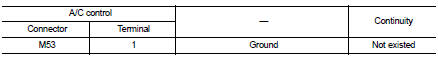
2.CHECK A/C SWITCH GROUND CIRCUIT FOR OPEN
1. Turn ignition switch OFF.
2. Disconnect BCM connector.
3. Check continuity between A/C control harness connector and ground.
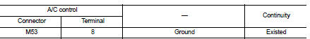
Is the inspection result normal? YES >> Replace A/C control. Refer to HAC-239, "Removal and Installation".
NO >> Repair harness or connector.
3.CHECK A/C SWITCH POWER SUPPLY CIRCUIT FOR OPEN
1. Turn ignition switch OFF.
2. Disconnect BCM connector.
3. Check continuity between A/C control harness connector and BCM harness connector.
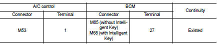
Is the inspection result normal? YES >> GO TO 4.
NO >> Repair harness or connector.
4.CHECK A/C SWITCH POWER SUPPLY CIRCUIT FOR SHORT
Check continuity between A/C control harness connector and ground.
Is the inspection result normal? YES >> Replace BCM. Refer to BCS-93, "Removal and Installation" (with Intelligent Key) or BCS-161, "Removal and Installation" (without Intelligent Key).
NO >> Repair harness or connector.

 Blower fan on signal
Component Function Check
1.CHECK BLOWER FAN ON SIGNAL
With CONSULT-III
1. Turn ignition switch ON.
2. Select “AIR CONDITIONER” of “BCM” using CONSULT-III.
3. Select “FAN ON SIG” in “DATA MONITOR” ...
Other materials:
B2621 inside antenna
DTC Logic
DTC DETECTION LOGIC
DTC CONFIRMATION PROCEDURE
1.PERFORM DTC CONFIRMATION PROCEDURE
1. Select “INTELLIGENT KEY” of “BCM” using CONSULT-III.
2. Select “INSIDE ANT DIAGNOSIS” in “WORK SUPPORT” mode.
3. Perform inside key antenna (“INSIDE ANT DIAGNOSIS”) on “WORK SUPPORT” of
“INTELL ...
CVT control system
Wiring diagram
For connector terminal arrangements, harness layouts, and alphabets in a
(option abbreviation; if not
described in wiring diagram), refer to GI-12, "Connector Information/Explanation
of Option Abbreviation".
...
ASCD indicator
Component Function Check
1.CHECK ASCD INDICATOR FUNCTION
Check ASCD indicator under the following conditions.
Is the inspection result normal?
YES >> INSPECTION END
NO >> Go to EC-767, "Diagnosis Procedure".
Diagnosis Procedure
1.CHECK DTC
Check that DTC UXXXX is not ...
