Nissan Juke Service and Repair Manual : A/C on signal
Component Function Check
1.CHECK A/C ON SIGNAL
 With CONSULT-III
1. Turn ignition switch ON.
2. Operate blower motor.
3. Select “AIR CONDITIONER” of “BCM” using CONSULT-III.
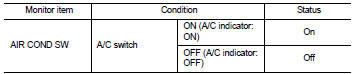
4. Select “AIR COND SW” in “DATA MONITOR” mode.
5. Check A/C ON signal when the A/C switch is operated.
Is the inspection result normal? YES >> INSPECTION END
NO >> Refer to HAC-75, "Diagnosis Procedure".
Diagnosis Procedure
1.CHECK A/C ON SIGNAL
1. Turn ignition switch OFF.
2. Disconnect A/C auto amp. connector.
3. Turn ignition switch ON.
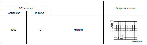
4. Check output waveform between A/C auto amp. harness connector and ground with using oscilloscope
Is the inspection result normal? YES >> Replace A/C auto amp. Refer to HAC-91, "Removal and Installation".
NO >> GO TO 2.
2.CHECK A/C ON SIGNAL CIRCUIT FOR OPEN
1. Turn ignition switch OFF.
2. Disconnect BCM connector.
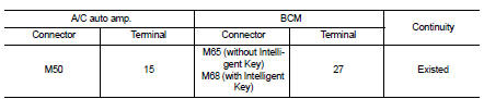
3. Check continuity between A/C auto amp. harness connector and BCM harness connector.
Is the inspection result normal? YES >> GO TO 3.
NO >> Repair harness or connector.
3.CHECK A/C ON SIGNAL CIRCUIT FOR SHORT
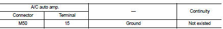
Check continuity between A/C auto amp. harness connector and ground.
Is the inspection result normal? YES >> Replace BCM. Refer to BCS-93, "Removal and Installation" (with Intelligent Key) or BCS-161, "Removal and Installation" (without Intelligent Key).
NO >> Repair harness or connector.
 Power supply and ground circuit
A/C auto AMP. : Diagnosis Procedure
1.CHECK SYMPTOM
Check symptom (A or B).
Which symptom is detected?
A >> GO TO 2.
B >> GO TO 5.
2.CHECK FUSE
1. Turn ignition switch OFF.
2 ...
 Blower fan on signal
Component Function Check
1.CHECK BLOWER FAN ON SIGNAL
With CONSULT-III
1. Turn ignition switch ON.
2. Select “AIR CONDITIONER” of “BCM” using CONSULT-III.
3. Select “FAN ON SIG” in “DATA MONITOR” ...
Other materials:
Hoses
HOSE REMOVAL AND INSTALLATION
• To prevent damage to rubber hose, do not pry off rubber hose with
tapered tool or screwdriver.
• To reinstall the rubber hose securely, check that hose insertion
length and orientation is correct. (If tube is equipped with hose
stopper, insert rubber hose into ...
U1000 can comm circuit
Description
CAN (Controller Area Network) is a serial communication line for real-time
application. It is an on-vehicle multiplex
communication line with high data communication speed and excellent malfunction
detection ability.
Many electronic control units are equipped onto a vehicle, and ...
U0100 lost communication (ECM A)
Description
CAN (Controller Area Network) is a serial communication line for real-time
application. It is an on-vehicle multiplex
communication line with high data communication speed and excellent malfunction
detection ability.
Many electronic control units are equipped onto a vehicle, and ...
