Nissan Juke Service and Repair Manual : A/C indicator
Diagnosis Procedure
1.CHECK SYMPTOM
Check symptom.
A/C indicator dose not turn ON>>GO TO 2.
A/C indicator dose not turn OFF>>GO TO 6.
2.CHECK FUSE
1. Turn ignition switch OFF.
2. Check 10A fuse (No. 15, located in fuse block (J/B)].
NOTE
:
Refer to PG-22, "Fuse, Connector and Terminal Arrangement".
Is the inspection result normal? YES >> GO TO 3.
NO >> Replace the blown fuse after repairing the affected circuit if a fuse is blown.
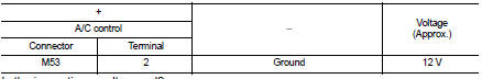
3.CHECK A/C INDICATOR POWER SUPPLY
1. Turn ignition switch ON.
2. Check voltage between A/C control harness connector and ground.

Is the inspection result normal? YES >> GO TO 4.
NO >> Repair harness or connector between A/C control and fuse.
4.CHECK A/C INDICATOR CIRCUIT
Check voltage between A/C control harness connector and ground.
Is the inspection result normal? YES >> GO TO 5.
NO >> Replace A/C control. Refer to HAC-304, "Removal and Installation".
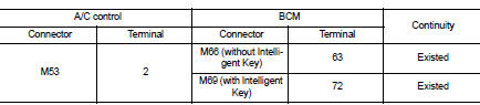
5.CHECK A/C INDICATOR CIRCUIT FOR OPEN
1. Turn ignition switch OFF.
2. Disconnect A/C control connector and BCM connector.
3. Check continuity between A/C control harness connector and BCM harness connector.
Is the inspection result normal? YES >> Replace BCM. Refer to BCS-93, "Removal and Installation" (with Intelligent Key) or BCS-161, "Removal and Installation" (without Intelligent Key).
NO >> Repair harness or connector.
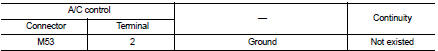
6.CHECK A/C INDICATOR CIRCUIT FOR SHORT
1. Turn ignition switch OFF.
2. Disconnect A/C control connector and BCM connector.
3. Check continuity between A/C control harness connector and ground.
Is the inspection result normal? YES >> Replace BCM. Refer to BCS-93, "Removal and Installation" (with Intelligent Key) or BCS-161, "Removal and Installation" (without Intelligent Key).
NO >> Repair harness or connector.
 Thermo control amplifier
Component Function Check
1.CHECK A/C ON SIGNAL
With CONSULT-III
1. Turn ignition switch ON.
2. Select “AIR CONDITIONER” of “BCM” using CONSULT-III.
3. Select “THERMO AMP” in “DATA MONITOR” mode, ...
 Blower motor
Diagnosis Procedure
1.CHECK SYMPTOM
Check symptom (A or B).
Which symptom is detected?
A >> GO TO 2.
B >> GO TO 7.
2.CHECK FUSE
1. Turn ignition switch OFF.
2. Check 15A fuse ...
Other materials:
P1650 starter motor relay 2
Description
ECM controls ON/OFF state of the starter relay, according to the engine and
vehicle condition. Models with no
Intelligent Key System transmit a control signal directly to IPDM E/R. On the
other hand, models with the Intelligent
Key System transmit a control signal to IPDM E/R by w ...
Fuel injector
Component Function Check
1.INSPECTION START
Turn ignition switch to START.
Is any cylinder ignited?
YES >> GO TO 2.
NO >> Go to EC-778, "Diagnosis Procedure".
2.CHECK FUEL INJECTOR FUNCTION
With CONSULT-III
1. Start engine.
2. Perform “POWER BALANCE” in “ACTIVE T ...
Radiator core supporT
HR16DE
HR16DE : Exploded View
1. Radiator core support upper
2. Air guide RH (MT models)
3. Radiator core support lower
4. Air guide LH
5. Air guide (upper)
6. Air guide LH (CVT models)
7. Air guide RH (CVT models)
: N·m (kg-m, ft-lb)
HR16DE : Removal and Installation
RADIATOR CORE ...
