Nissan Juke Service and Repair Manual : A/C indicator
Diagnosis Procedure
1.CHECK SYMPTOM
Check symptom.
A/C indicator dose not turn ON>>GO TO 2.
A/C indicator dose not turn OFF>>GO TO 6.
2.CHECK FUSE
1. Turn ignition switch OFF.
2. Check 10A fuse (No. 15, located in fuse block (J/B)].
NOTE
:
Refer to PG-22, "Fuse, Connector and Terminal Arrangement".
Is the inspection result normal? YES >> GO TO 3.
NO >> Replace the blown fuse after repairing the affected circuit if a fuse is blown.
3.CHECK A/C INDICATOR POWER SUPPLY
1. Turn ignition switch ON.
2. Check voltage between A/C control harness connector and ground.
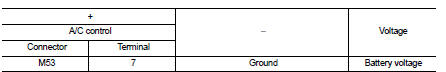
Is the inspection result normal? YES >> GO TO 4.
NO >> Repair harness or connector between A/C control and fuse.
4.CHECK A/C INDICATOR CIRCUIT
Check voltage between A/C control harness connector and ground.
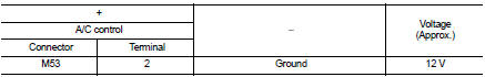
Is the inspection result normal? YES >> GO TO 5.
NO >> Replace A/C control. Refer to HAC-239, "Removal and Installation".
5.CHECK A/C INDICATOR CIRCUIT FOR OPEN
1. Turn ignition switch OFF.
2. Disconnect A/C control connector and BCM connector.
3. Check continuity between A/C control harness connector and BCM harness connecto
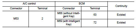
Is the inspection result normal? YES >> Replace BCM. Refer to BCS-93, "Removal and Installation" (with Intelligent Key) or BCS-161, "Removal and Installation" (without Intelligent Key).
NO >> Repair harness or connector.
6.CHECK A/C INDICATOR CIRCUIT FOR SHORT
1. Turn ignition switch OFF.
2. Disconnect A/C control connector and BCM connector.
3. Check continuity between A/C control harness connector and ground.
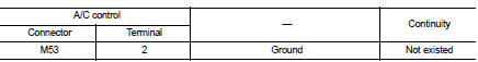
Is the inspection result normal? YES >> Replace BCM. Refer to BCS-93, "Removal and Installation" (with Intelligent Key) or BCS-161, "Removal and Installation" (without Intelligent Key).
NO >> Repair harness or connector
 Thermo control amplifier
Component Function Check
1.CHECK A/C ON SIGNAL
With CONSULT-III
1. Turn ignition switch ON.
2. Select “AIR CONDITIONER” of “BCM” using CONSULT-III.
3. Select “THERMO AMP” in “DATA MONITOR” mode, ...
 Blower motor
Diagnosis Procedure
1.CHECK SYMPTOM
Check symptom (A or B).
Which symptom is detected?
A >>GO TO 2.
B >>GO TO 7.
2.CHECK FUSE
1. Turn ignition switch OFF.
2. Check 15A fuses ...
Other materials:
Wiring diagram
CAN SYSTEM
Wiring Diagram
For connector terminal arrangements, harness layouts, and alphabets in a
(option abbreviation; if not
described in wiring diagram), refer to GI-12, "Connector Information/Explanation
of Option Abbreviation".
...
B260B steering lock unit
DTC Logic
DTC DETECTION LOGIC
DTC CONFIRMATION PROCEDURE
1.PERFORM DTC CONFIRMATION PROCEDURE
1. Turn ignition switch ON.
2. Turn ignition switch OFF.
3. Press driver side door switch.
4. Shift selector lever to the P position.
5. Press push-button ignition switch under the following condi ...
P2080 EGT sensor 1
DTC Logic
DTC DETECTION LOGIC
Diagnosis Procedure
1.CHECK GROUND CONNECTIONS
1. Turn ignition switch OFF.
2. Check ground connection E38. Refer to Ground inspection in GI-44, "Circuit
Inspection".
Is the inspection result normal?
YES >> GO TO 2.
NO >> Repair or ...
