Nissan Juke Service and Repair Manual : 4WD branch line circuit
Diagnosis Procedure
1.CHECK CONNECTOR
1. Turn the ignition switch OFF.
2. Disconnect the battery cable from the negative terminal.
3. Check the following terminals and connectors for damage, bend and loose connection (unit side and connector side).
- 4WD control module
- Harness connecotor B7
- Harness connecotor E107
Is the inspection result normal? YES >> GO TO 2.
NO >> Repair the terminal and connector.
2.CHECK HARNESS FOR OPEN CIRCUIT
1. Disconnect the connector of 4WD control module.
2. Check the resistance between the 4WD control module harness connector terminals.
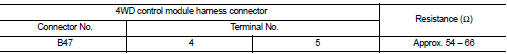
Is the measurement value within the specification? YES >> GO TO 3.
NO >> Repair the 4WD control module branch line.
3.CHECK POWER SUPPLY AND GROUND CIRCUIT
Check the power supply and the ground circuit of the 4WD control module. Refer to DLN-78, "Diagnosis Procedure".
Is the inspection result normal? YES (Present error)>>Replace the 4WD control module. Refer to DLN-91, "Removal and Installation".
YES (Past error)>>Error was detected in the 4WD control module branch line.
NO >> Repair the power supply and the ground circuit.
 ECM branch line circuit
Diagnosis Procedure
1.CHECK CONNECTOR
1. Turn the ignition switch OFF.
2. Disconnect the battery cable from the negative terminal.
3. Check the terminals and connectors of the ECM for damage, bend ...
 ABS branch line circuit
Diagnosis Procedure
1.CHECK CONNECTOR
1. Turn the ignition switch OFF.
2. Disconnect the battery cable from the negative terminal.
3. Check the terminals and connectors of the ABS actuator and ele ...
Other materials:
Engine control system
Symptom Table
SYSTEM — BASIC ENGINE CONTROL SYSTEM
1 - 6: The numbers refer to the order of inspection.
(continued on next page)
SYSTEM — ENGINE MECHANICAL & OTHER
1 - 6: The numbers refer to the order of inspection. ...
Steering switch ground circuit
Description
Transmits the steering switch signal to audio unit.
Diagnosis Procedure
1.CHECK STEERING SWITCH SIGNAL GROUND CIRCUIT
1. Disconnect audio unit connector and spiral cable connector.
2. Check continuity between audio unit harness connector and spiral cable
harness connector.
Is t ...
Integrated control system (if so equipped)
The Integrated Control System is located below the audio system or navigation
system (if so equipped). Two Integrated Control System modes can be selected: Drive
mode and Climate Control mode.
Depending on which Integrated Control System mode selected (Drive mode or Climate
Control mode), the ...
