Nissan Juke Service and Repair Manual : Wiring diagram
Engine control system
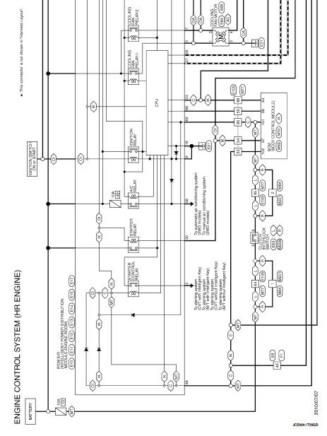
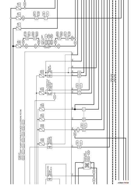
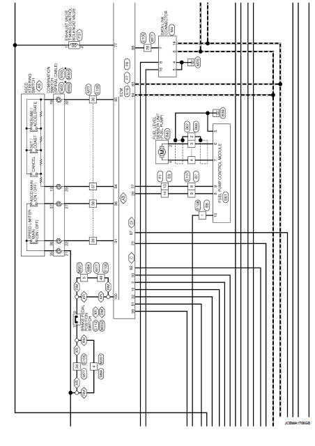
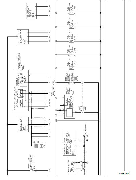
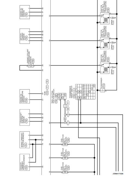
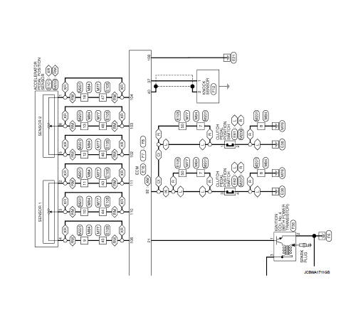
Wiring Diagram
For connector terminal arrangements, harness layouts, and alphabets in a
 (option abbreviation; if not
described in wiring diagram), refer to GI-12, "Connector Information/Explanation
of Option Abbreviation".
 ECU diagnosis information
ECM
Reference Value
VALUES ON THE DIAGNOSIS TOOL
Remarks:
• Specification data are reference values.
• Specification data are output/input values which are detected or supplied by
the ECM at th ...
 Basic inspection
...
Other materials:
Side turn signal lamp
Exploded View
1. Side turn signal lamp bulb
2. Side turn signal lamp hous
Removal and Installation
CAUTION:
Disconnect battery negative terminal or remove the fuse.
REMOVAL
1. Remove the side turn signal lamp in numerical order shown in
the figure.
2. Rotate the bulb socket counterclockw ...
System
Warning chime system
WARNING CHIME SYSTEM : System Diagram
WARNING CHIME SYSTEM : System Description
COMBINATION METER
The combination meter sounds the alarm buzzer installed in the combination
meter when receiving the buzzer
output signal transmitted from each unit.
BCM
BCM receives si ...
P0335 CKP sensor (POS)
DTC Logic
DTC DETECTION LOGIC
Diagnosis Procedure
1.CHECK GROUND CONNECTIONS
1. Turn ignition switch OFF.
2. Check ground connection E38. Refer to Ground inspection in GI-44, "Circuit
Inspection".
Is the inspection result normal?
YES >> GO TO 2.
NO >> Repair or ...
