Nissan Juke Service and Repair Manual : Wiring diagram
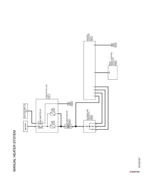
MANUAL HEATER SYSTEM
Wiring Diagram
For connector terminal arrangements, harness layouts, and alphabets in a
 (option abbreviation; if not
described in wiring diagram), refer to GI-12, "Connector Information/Explanation
of Option Abbreviation".
 ECU diagnosis information
BCM
List of ECU Reference
...
 Basic inspection
...
Other materials:
Diagnosis and repair workflow
Gasoline engine models
GASOLINE ENGINE MODELS : Work Flow
OVERALL SEQUENCE
DETAILED FLOW
1.PRELIMINARY INSPECTION
Perform the preliminary inspection. Refer to CHG-17, "Inspection Procedure".
Models with battery current sensor>>GO TO 2.
Models without battery current sens ...
Fog light switch (if so equipped)
To turn the fog lights on, turn the headlight switch to the
position, then turn the switch to the
position. To turn them off, turn the
switch to the OFF position.
The headlights must be on for the fog lights to operate.
When the headlight switch is in the AUTO position, turning the fog lig ...
System
System Diagram
System Description
DESCRIPTION
• Manual air conditioning system is controlled by each function of thermo
control amp., BCM, ECM and IPDM
E/R.
• Fan speed of blower motor is changed by the combination of fan control dial
operation and blower fan resistor
control.
CONTROL ...
