Nissan Juke Service and Repair Manual : Wiring diagram
SRS AIR BAG SYSTEM
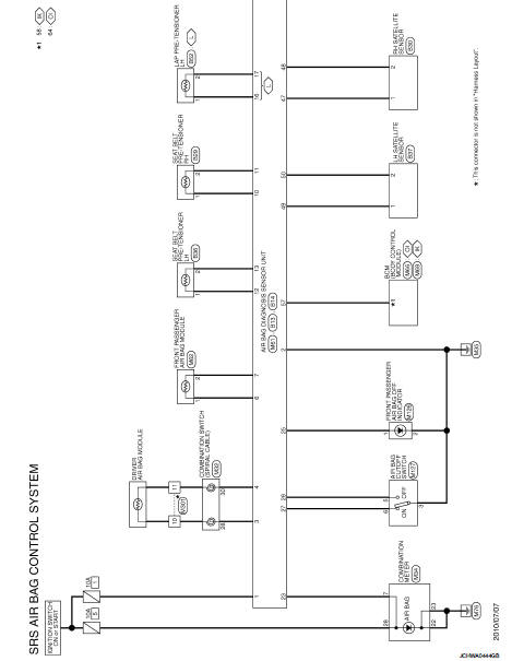
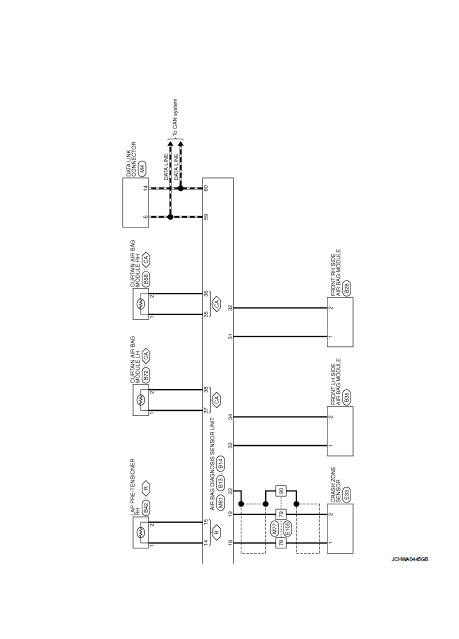
Wiring Diagram
For connector terminal arrangements, harness layouts, and alphabets in a
 (option abbreviation; if not
described in wiring diagram), refer to GI-12, "Connector Information/Explanation
of Option Abbreviation".
 ECU diagnosis information
DIAGNOSIS SENSOR UNIT
DTC Index
...
 Basic inspection
DIAGNOSIS AND REPAIR WORK FLOW
Work Flow
OVERALL SEQUENCE
DETAILED FLOW
1.INTERVIEW THE CUSTOMER FOR THE SYMPTOM
Interview the customer for the symptom (the condition and the environment
when ...
Other materials:
Body alignment
Body Center Marks (RHD Models)
A mark is placed on each part of the body to indicate the vehicle center.
When repairing the vehicle frame
(members, pillars, etc.) damaged by an accident which it enables more accurate
and effective repair by using
these marks together with body alignment speci ...
System description
COMPONENT PARTS
Circuit Breaker
The PTC thermistor generates heat in response to current flow. The
temperature (and resistance) of the thermistor element varies with
current flow. Excessive current flow will cause the element's temperature
to rise. When the temperature reaches a specified level ...
P1574 ASCD vehicle speed sensor
Description
The ECM receives two vehicle speed sensor signals via CAN communication line.
One is sent from combination
meter, and the other is from TCM (Transmission control module). The ECM uses
these signals for ASCD
control. Refer to EC-477, "AUTOMATIC SPEED CONTROL DEVICE (ASCD) : Sy ...
