Nissan Juke Service and Repair Manual : Wheel alignment
Inspection
DESCRIPTION
CAUTION:
• The adjustment mechanisms of camber, caster, and kingpin inclination angles
are not included.
• If camber, caster, or kingpin inclination angle is outside the standard, check front suspension parts for wear and damage. Replace suspect parts if a malfunction is detected.
• Kingpin inclination angle is reference value, no inspection is required.
Measure wheel alignment under unladen conditions.
NOTE:
“Unladen conditions” means that fuel, engine coolant, and lubricant are full. Spare tire, jack, hand tools and mats are in designated positions.
PRELIMINARY CHECK
Check the following:
• Tires for improper air pressure and wear.
• Road wheels for runout. Refer to WT-7, "Inspection".
• Wheel bearing axial end play. Refer to FAX-9, "Inspection".
• Transverse link ball joint axial end play. Refer to FSU-14, "Inspection".
• Strut operation.
• Each mounting part of axle and suspension for looseness and deformation.
• Each of suspension member, strut and transverse link for cracks, deformation and other damage.
• Vehicle height (posture).
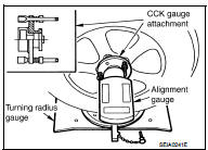
CAMBER, CASTER, AND KINGPIN INCLINATION ANGLES
Before inspection, mount front wheels onto turning radius gauge. Mount rear wheels onto a stand at the same height so that vehicle remains horizontal.
Using a CCK Gauge
Install the CCK gauge attachment (SST: KV991040S1) with the following procedure
on wheel, then measure
wheel alignment.
1. Remove three wheel to nuts, and install the guide bolts to hub bolt.
2. Screw the adapter into the plate until it contacts the plate tightly.
3. Screw the center plate into the plate.
4. Insert the plate assembly on the guide bolt. Put the spring in, and then evenly screw the three guide bolt nuts. When fastening the guide nuts, do not completely compress the spring.
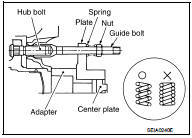
5. Place the dent of alignment gauge onto the projection of the center plate and tightly contact them to measure.
Camber, caster, kingpin inclination angles : Refer to FSU-21, "Wheel Alignment".
CAUTION:
• If camber, caster, or kingpin inclination angle exceeds the
standard value, check front suspension parts for wear and
damage. Replace suspect parts if a malfunction is
detected.
• Kingpin inclination angle is reference value, no inspection is required.
TOE-IN
Measure toe-in by the following procedure.
WARNING:
• Always perform the following procedure on a flat surface.
• Check that no person is in front of vehicle before pushing it.
1. Bounce front of vehicle up and down to stabilize the vehicle height (posture).
2. Push vehicle straight ahead about 5 m (16 ft).
3. Put matching mark (A) on base line of the tread (rear side) of both tires at the same height of hub center. These are measuring points.
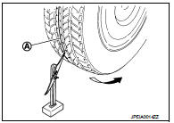
4. Measure distance (A) (rear side).
 : Vehicle front
5. Push vehicle slowly ahead to rotate wheels 180 degrees (1/2 turn).
NOTE
:
If the wheels rotates more than 180 degrees (1/2 turn), start this
procedure again from the beginning. Do not push the vehicle
backward.
6. Measure distance (B) (front side).
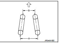
Total toe-in = A – B
Total toe-in : Refer to FSU-21, "Wheel Alignment".
• If toe-in exceeds the standard value, adjust toe-in by varying the length of between steering outer socket and inner socket.
 Front suspension assembly
Inspection
COMPONENT PART
Check the mounting conditions (looseness, backlash) of each component and
component conditions (wear,
damage) are normal.
BALL JOINT AXIAL END PLAY
1. Set front whee ...

Other materials:
ANTI-HIJACK function does not operate
Diagnosis Procedure
1.CHECK “DOOR LOCK–UNLOCK SET” SETTING IN “WORK SUPPORT”
1. Select “DOOR LOCK” of “BCM” using CONSULT-III.
2. Select “DOOR LOCK-UNLOCK SET” in “WORK SUPPORT” mode.
3. Check “DOOR LOCK-UNLOCK SET” in “WORK SUPPORT”
Refer to DLK-217, "DOOR LOCK : CONSULT-III Function (BCM ...
Components
• THE LARGE ILLUSTRATIONS are exploded views (see the following) and
contain tightening torques, lubrication
points, section number of the PARTS CATALOG (e.g. SEC. 440) and other
information necessary to
perform repairs.
The illustrations should be used in reference to service matters only. ...
Additional service when replacing ECM
Description
When replacing ECM, this procedure must be performed.
Work Procedure
1.PERFORM INITIALIZATION OF NATS SYSTEM AND REGISTRATION OF ALL NATS
IGNITION KEY IDS
Refer to SEC-50, "BCM : Special Repair Requirement" (With intelligent key
system), SEC-190, "BCM : Work
Proce ...
