Nissan Juke Service and Repair Manual : Water outlet
Exploded View
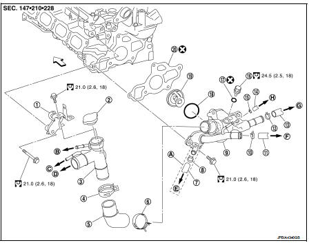
1. Heater pipe bracket
2. Radiator cap
3. Water outlet adaptor
4. Clamp
5. Water outlet hose
6. Clamp
7. Heater hose
8. Clamp
9. Water outlet
10. Clamp
11. Heater hose
12. Heater hose
13. Clamp
14. Heater hose
15. Clamp
16. Engine coolant temperature sensor
17. Gasket
18. Rubber ring
19. Water control value
20. Gasket
 Engine front
A. For CVT models
B. To reservoir tank
C. To heater hose
D. To radiator hose (upper)
E. To CVT oil warmar
F. To heater hose
G. To heate hose
H. To turbocharger inlet tube
 : N·m (kg-m, ft-lb)
 : Always replace after every
disassembly.
Removal and Installation
REMOVAL
1. Drain engine coolant from radiator. Refer to CO-11, "Draining".
CAUTION:
• Perform this step when engine is cold.
2. Remove engine cover. Refer to EM-25, "Exploded View".
3. Remove battery. PG-124, "Exploded View".
4. Remove air duct (duct side) and air cleaner cover assembly and air cleaner body assembly.
5. Disconnect radiator hose (upper). Refer to CO-17, "Exploded View".
6. Remove water outlet adaptor.
7. Disconnect connectors of engine harness around the battery.
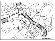
8. Remove bracket (2), and disconnect engine harness clip.(transmission side and water outlet side) 9. Disconnect crankshaft position sensor harness connector.
10. Move engine (1) harness, and keep a service area.
11. Remove water hose and heater hose.
12. Remove water outlet.
13. Remove engine coolant temperature sensor from water outlet, if necessary.
INSTALLATION
Note the following, and install in the reverse order of removal.
Water Control valve
• Install water control valve with making rubber ring (1) groove fit to
water control valve flange (A) with the whole circumference.
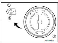
• Install water control valve (2) with the arrow (A) facing up and the frame center part (B) facing upwards.
1 : Water control valve
Inspection
INSPECTION AFTER REMOVAL
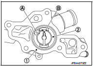
Water Control Valve
• Place a thread (A) so that it is caught in the valves of water control valve (1). Immerse fully in a container (B) filled with water. Heat while stirring.
• The valve opening temperature is the temperature at which the valve opens and falls from the thread.
• Continue heating. Check the continuous valve lifting toward maximum valve lift.
NOTE
:
The maximum valve lift amount standard temperature for water
control valve is the reference value.
• After checking the maximum valve lift amount, lower the water temperature and check the valve closing temperature.
Standard: Refer to CO-29, "Water Control Valve".
• If out of the standard, replace water control valve.
INSPECTION AFTER INSTALLATION
• Check for leakage of engine coolant using the radiator cap tester adapter (commercial service tool) and the radiator cap tester (commercial service tool). Refer to CO-11, "Inspection".
• Start and warm up the engine. Check visually that there is no leakage of engine coolant.
 Thermostat
Exploded View
1. Thermostat housing
2. Gasket
3. Rubber ring
4. Thermostat
5. Water inlet
6. Clamp
7. Radiator hose (upper)
A. To radiator
Engine front
: N·m (kg-m, ft-lb)
: Always ...

Other materials:
Direct injection gasoline system
Direct injection gasoline system : System Diagram
Direct injection gasoline system : System Description
INPUT/OUTPUT SIGNAL CHART
*1: This sensor is not used to control the engine system under normal
conditions.
*2: CVT models
*3: M/T models
*4: ECM determines the start signal status by ...
Precaution for Supplemental Restraint System (SRS) "AIR BAG" and "SEAT BELT
PRE-TENSIONER"
The Supplemental Restraint System such as “AIR BAG” and “SEAT BELT PRE-TENSIONER”,
used along
with a front seat belt, helps to reduce the risk or severity of injury to the
driver and front passenger for certain
types of collision. Information necessary to service the system safely is
include ...
P245A EGR cooler bypass valve control solenoid valve
DTC Logic
DTC DETECTION LOGIC
NOTE:
If DTC P245A is displayed with DTC P0560 or P0657, first perform trouble
diagnosis for DTC P0560 or P0657.
Refer to EC-963, "DTC Logic" (DTC P0560) or EC-976, "DTC Logic" (DTC P0657).
Diagnosis Procedure
1.CHECK GROUND CONNECTIONS
...
