Nissan Juke Service and Repair Manual : Vacuum lines
MR16DDT : Removal and Installation
REMOVAL
1. Remove the vacuum hose and vacuum piping.
2. Perform inspection after removal. Refer to BR-115, "MR16DDT : Inspection".
INSTALLATION
Note the following, install the vacuum hose.
• When installing vacuum hose, insert it until its tip reaches the back-end of length (A) or further as shown in the figure.
CAUTION:
Never use lubricating oil during assembly.
A : 24 mm (0.95 in) or more
- Face the paint mark of vacuum hose (engine side) upward to assemble.
- Face the paint mark of vacuum hose (brake booster side) to the vehicle front side to assemble.
- For clamp mounting direction (the orientation of pawl), refer to BR- 115, "MR16DDT : Exploded View".
MR16DDT : Inspection
INSPECTION AFTER REMOVAL
Appearance
Check for correct assembly, damage and deterioration.
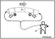
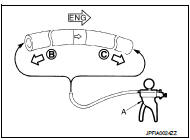
Check Valve Airtightness • Use a handy vacuum pump (A) to check.
When connected to the booster side (B): Vacuum should decrease within 1.3 kPa (9.8 mmHg, 0.38 inHg, 0.013 bar) for 15 seconds under a vacuum of −66.7 kPa (−500 mmHg, −19.70 inHg, −0.667 bar).
When connected to the engine side (C): Vacuum should not exist.
• Replace vacuum hose if vacuum hose is malfunctioning.
HR16DE : Exploded View
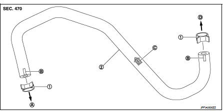
1. Clamp
2. Vacuum hose (built-in check valve)
A. To intake manifold
B. Paint mark
C. Stamp indicating engine direction
D. To brake booster
HR16DE : Removal and Installation
REMOVAL
1. Remove the vacuum hose and vacuum piping.
2. Perform inspection after removal. Refer to BR-117, "HR16DE : Inspection".
INSTALLATION
Note the following, install the vacuum hose.
• When installing vacuum hose, insert it until its tip reaches the back-end of length (A) or further as shown in the figure.
CAUTION:
Never use lubricating oil during assembly.
A : 24 mm (0.95 in) or more
- Face the paint marks upward to assemble.
- For clamp mounting direction (the orientation of pawl), refer to BR- 116, "HR16DE : Exploded View".
HR16DE : Inspection
INSPECTION AFTER REMOVAL
Appearance
Check for correct assembly, damage and deterioration.
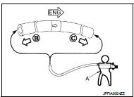
Check Valve Airtightness • Use a handy vacuum pump (A) to check.
When connected to the booster side (B): Vacuum should decrease within 1.3 kPa (9.8 mmHg, 0.38 inHg, 0.013 bar) for 15 seconds under a vacuum of −66.7 kPa (−500 mmHg, −19.70 inHg, −0.667 bar).
When connected to the engine side (C): Vacuum should not exist.
• Replace vacuum hose assembly if vacuum hose and check valve are malfunctioning.
K9K : Exploded View
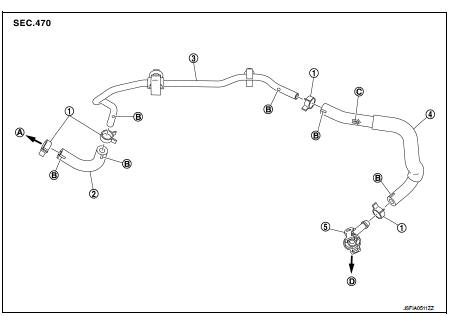
1. Clamp
2. Vacuum hose
3. Vacuum piping
4. Vacuum hose (built-in check valve)
5. Connector
A. To brake booster
B. Paint mark
C. Stamp indicating engine direction
D. To vacuum pump
K9K : Removal and Installation
REMOVAL
1. Remove air duct and air cleaner case. Refer to EM-280, "Removal and Installation".
2. Remove the vacuum hose and connector.
INSTALLATION
Note the following, install the vacuum hose.
• When installing vacuum hose, insert it until its tip reaches the back-end of length (A) or further as shown in the figure.
CAUTION:
Never use lubricating oil during assembly.
A : 24 mm (0.95 in) or more
- Face the paint mark of vacuum hose (built-in check valve, connector side) upward to assemble.
- Face the other paint marks to vehicle front side to assemble.
- For clamp mounting direction (the orientation of pawl), refer to BR- 117, "K9K : Exploded View".
K9K : Inspection
INSPECTION AFTER REMOVAL
Appearance
Check for correct assembly, damage and deterioration.
Check Valve Airtightness • Use a handy vacuum pump (A) to check.
When connected to the booster side (B): Vacuum should decrease within 1.3 kPa (9.8 mmHg, 0.38 inHg, 0.013 bar) for 15 seconds under a vacuum of −66.7 kPa (−500 mmHg, −19.70 inHg, −0.667 bar).
When connected to the engine side (C): Vacuum should not exist.
• Replace vacuum hose assembly if vacuum hose and check valve are malfunctioning.
 Brake booster
Exploded View
2WD
MR16DDT, HR16DE
1. Master cylinder assembly
2. Vacuum pipe
3. Brake booster
4. Lock nut
5. Clevis
6. Gasket
: N·m (kg-m, ft-lb)
K9K
1. Master cylinder assembly
2 ...
 Front disc brake
Brake pad : Exploded View
MR16DDT
1. Cylinder body
2. Inner shim
3. Inner pad (with pad wear sensor)
4. Pad retainer
5. Torque member
6. Outer pad
7. Outer shim
1: Apply MOLYKOTE® AS880 ...
Other materials:
P2122, P2123 APP sensor
DTC Logic
DTC DETECTION LOGIC
NOTE:
If DTC P2122 or P2123 is displayed with DTC P0643, first perform the trouble
diagnosis for DTC P0643.
Refer to EC-686, "DTC Logic".
DTC CONFIRMATION PROCEDURE
1.PRECONDITIONING
If DTC Confirmation Procedure has been previously conducted, alw ...
P0847 transmission fluid pressure SEN/SW B
DTC Logic
DTC DETECTION LOGIC
DTC CONFIRMATION PROCEDURE
1.PREPARATION BEFORE WORK
If another "DTC CONFIRMATION PROCEDURE" occurs just before, turn ignition
switch OFF and wait for at
least 10 seconds, then perform the next test.
>> GO TO 2.
2.CHECK DTC DETECTION
With ...
Refilling
1. Install reservoir tank if removed and radiator drain plug.
CAUTION:
Be sure to clean drain plug and install with new O-ring.
Radiator drain plug : Refer to CO-42, "Exploded View".
• If water drain plugs on cylinder block are removed, close and tighten them.
Refer to EM-228, &quo ...
