Nissan Juke Service and Repair Manual : Unit removal and installation
TRANSMISSION ASSEMBLY
Exploded View
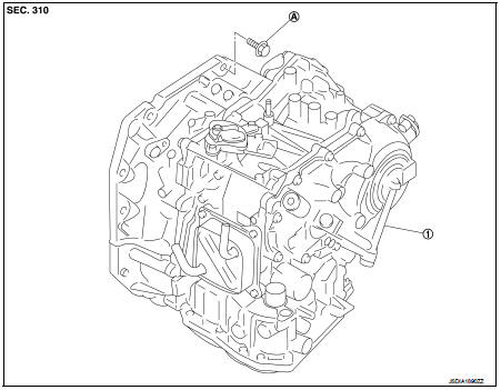
1. Transaxle assembly
A: : For the tightening torque, refer to TM-508, "Removal and Installation".
Removal and Installation
REMOVAL
WARNING:
Never open the radiator cap or drain plug when the engine is hot. Hot liquid may
spray out, causing
serious injury.
CAUTION:
Perform these steps after the coolant temperature has cooled sufficiently.
NOTE:
• When replacing the TCM and transaxle assembly as a set, replace the transaxle assembly first and then replace the TCM. Refer to TM-374, "Description".
• Cap or plug openings to prevent fluid from spilling.
1. Remove the battery. Refer to PG-124, "Exploded View".
2. Remove the air cleaner case. Refer to EM-161, "Removal and Installation".
3. Remove the ECM and bracket as a set.
4. Disconnect the connectors and harnesses.
• For CVT unit connector, refer to TM-311, "Removal and Installation Procedure for CVT Unit Connector".
• Transmission position switch connector • Primary pulley speed sensor connector • Secondary pulley speed sensor connector • Output speed sensor connector • Ground
5. Disconnect the control cable from the transaxle assembly. Refer to TM-485, "Removal and Installation".
6. Remove the water hose from the engine side. TM-500, "Removal and Installation".
NOTE
:
Coolant leaks out. Use a cap, plug, or other means to prevent leakage.
7. Remove starter motor. Refer to STR-22, "HR16DE : Removal and Installation".
8. Remove the left and right fender protector. Refer to EXT-22, "Removal and Installation".
9. Rotate the crankshaft and remove the nuts that secure the drive plate to the torque converter from the stator motor mount.
CAUTION:
Rotate crankshaft clockwise (as viewed from the front of the engine).
10. Remove the left and right drive shafts. Refer to FAX-53, "Removal and Installation".
11. Remove the front suspention member. Refer to FSU-18, "Removal and Installation".
12. Remove the heat insulator. Refer to EX-12, "Exploded View".
13. Set a transmission jack under the transaxle assembly.
CAUTION:
Be careful not to contact the drain plug when setting the transmission jack.
14. Set a transmission jack under the engine assembly.
CAUTION:
Be careful not to contact the drain plug when setting the transmission jack.
15. Remove the left engine mounting insulator and left engine mounting bracket as a set. Refer to EM-215, "Exploded View".
16. Remove the bolts that fasten the transaxle assembly and engine assembly.
17. Remove the transaxle assembly from the vehicle.
CAUTION:
Never drop the torque converter.
INSTALLATION
Note the following, and install in the reverse order of removal.
CAUTION:
• Never reuse O-ring.
• Apply Vaseline to the O-ring.
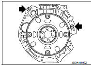
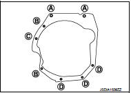
• When installing the transaxle assembly onto the engine assembly,
check the engagement of the dowel pin (
).
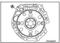
• When using drive plate location guide, install drive plate location guide (Commercial service tool: 31197EU50A) (A) to drive plate location guide mounting part of torque converter.
• Rotate the crankshaft so that the drive plate location guide insert hole (A) of the drive plate is aligned with the drive plate location guide that is installed on the torque converter.
CAUTION:
• Rotate the crankshaft clockwise (as viewed from the front of
the engine).
• Be careful that torque converter stud bolt is aligned to drive plate hole position. Otherwise stud bolt contacts drive plate.
• Temporally tighten drive plate and torque converter connecting nuts and tighten to the specified torque.
Tightening torque : 51 N·m (5.2 kg-m, 38 ft-lb)
CAUTION:
• Rotate crankshaft clockwise (as viewed from the front of the engine).
• Check the tightening torque for the crankshaft pulley mounting bolts after the bolts fastening the drive plate and torque converter have been tightened and the crankshaft pulley mounting bolts have been secured. Refer to EM-182, "Removal and Installation".
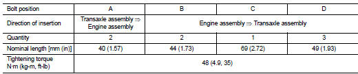
• Install the transaxle assembly and engine assembly mounting bolts according to the following standards.
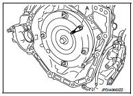
Inspection and Adjustment
INSPECTION BEFORE INSTALLATION
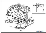
Check the distance “A”between the converter housing and torque converter.
B : Scale
C : Straightedge
Dimension “A” : TM-513, "Torque Converter"
INSPECTION AFTER INSTALLATION
Check the following items: • CVT fluid leakage. Refer to TM-480, "Inspection" • For CVT position, refer to TM-383, "Inspection and Adjustment".
• Start the engine and check for coolant leakage from the parts which are removed and reinstalled.
ADJUSTMENT AFTER INSTALLATION
• Adjust the CVT fluid level. TM-379, "Adjustment".
• Perform "ADDITIONAL SERVICE WHEN REPLACE TRANSAXLE ASSEMBLY". Refer to TM-375, "Description".
 Plug
Plug
Description
Replace the O-ring if oil leakage or exudes from the plug.
Exploded View
1. Plug
2. O-ring
3. O-ring
4. Plug
: Always replace after every
disassembly.
: N·m (kg-m, ft-lb)
: ...

Other materials:
P1217 engine over temperature
DTC Logic
DTC DETECTION LOGIC
NOTE:
• If DTC P1217 is displayed with DTC UXXXX, first perform the trouble diagnosis
for DTC UXXXX.
• If DTC P1217 is displayed with DTC P0607, first perform the trouble diagnosis
for DTC P0607. Refer
to EC-304, "DTC Logic".
If the cooling fan or ...
Insufficient heating
Description
Symptom
• Insufficient heating
• No warm air comes out. (Air flow volume is normal.)
Diagnosis Procedure
NOTE:
Perform self-diagnosis with CONSULT-III before performing symptom diagnosis. If
any malfunction result or
DTC is detected, perform the corresponding diagnosis.
1.CHE ...
Engine stand setting
Preparing the engine to be on the stand
Before the engine is mounted on the engine sub-attachment, the engine's
electrical harness must be removed
and the engine oil drained.
1. Remove the multifunction support.
2. Remove the coolant inlet pipe on the water pump.
3. Place the rods (A), ...
