Nissan Juke Service and Repair Manual : U1119 lost comm (multi-display)
Description
CAN (Controller Area Network) is a serial communication line for real-time application. It is an on-vehicle multiplex communication line with high data communication speed and excellent malfunction detection ability.
Many electronic control units are equipped onto a vehicle, and each control unit shares information and links with other control units during operation (not independently). In CAN communication, control units are connected with 2 communication lines (CAN-H line, CAN-L line) allowing a high rate of information transmission with less wiring. Each control unit transmits/receives data but selectively reads required data only.
DTC Logic
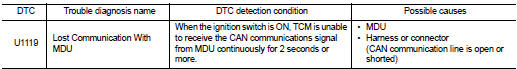
DTC DETECTION LOGIC
DTC CONFIRMATION PROCEDURE
1.PREPARATION BEFORE WORK
If another "DTC CONFIRMATION PROCEDURE" occurs just before, turn ignition switch OFF and wait for at least 10 seconds, then perform the next test.
>> GO TO 2.
2.PERFORM DTC CONFIRMATION PROCEDURE
 With CONSULT-III
1. Start the engine and wait for 5 seconds or more.
2. Check the DTC.
Is “U1119” detected? YES >> Go to TM-392, "Diagnosis Procedure".
NO >> INSPECTION END
Diagnosis Procedure
For the diagnosis procedure, refer to LAN-17, "Trouble Diagnosis Flow Chart".
 U1117 lost communication (ABS)
Description
CAN (Controller Area Network) is a serial communication line for real-time
application. It is an on-vehicle multiplex
communication line with high data communication speed and excellen ...
 P062f eeprom
DTC Logic
DTC DETECTION LOGIC
DTC CONFIRMATION PROCEDURE
1.PREPARATION BEFORE WORK
If another "DTC CONFIRMATION PROCEDURE" occurs just before, turn ignition
switch OFF and wait for a ...
Other materials:
B2626 OUTSIDE ANTENNA
DTC Logic
DTC DETECTION LOGIC
DTC CONFIRMATION PROCEDURE
1.PERFORM DTC CONFIRMATION PROCEDURE
1. Disconnect outside key antenna (driver side) connector.
2. Perform “INTELLIGENT KEY” Self Diagnostic Result.
Is outside key antenna DTC detected?
YES >> Refer to DLK-236, "Diagnosis ...
Wiring diagram
WARNING CHIME SYSTEM
Wiring Diagram
For connector terminal arrangements, harness layouts, and alphabets in a
(option abbreviation; if not
described in wiring diagram), refer to GI-12, "Connector Information/Explanation
of Option Abbreviation".
...
Removal and installation
Exhaust system
Exploded View
2WD
1. Center muffler
2. Mounting rubber
3. Spring
4. Seal bearing
5. Stud bolt
6. Three way catalyst
7. Heated oxygen sensor 2
8. Seal bearing
9. Ring gasket
10. Main muffler
A. To catalyst convertor
: N·m (kg-m, ft-lb)
: Always replace after ever ...
