Nissan Juke Service and Repair Manual : Turbocharger
Exploded View
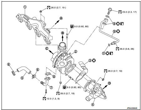
1. Exhaust manifold
2. Turbocharger
3. Gasket
4. Turbocharger outlet duct
5. Oil outlet hose
6. Clamp
7. Oil return pipe
8. Gasket
9. Washer
10. Oil supply tube
11. O-ring
A. To EGR tube
B. To air inlet pipe
C. To turbocharge air inlet pipe
D. To diesel particular filter assembly
 : N·m (kg-m, ft-lb)
 : N·m (kg-m, in-lb)
 : Always replace after every
disassembly.
 : Should be lubricated with oil.
Removal and Installation
REMOVAL
1. Remove air cleaner case. Refer to EM-280, "Exploded View".
2. Remove cowl top extension. Refer to EXT-20, "Exploded View".
3. Drain engine coolant. Refer to CO-62, "Draining".
4. Remove diesel particular filter assembly. Refer to EX-17, "Exploded View".
5. Remove EGR volume control valve housing. Refer to EM-283, "Exploded View".
6. Remove EGR cooler.
7. Disconnect 5th injector quick connector and harness connector.
8. Remove oil tubes.
9. Remove turbocharger outlet duct bracket.
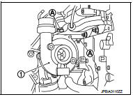
10. Remove turbocharger assembly (1) as follows:
NOTE
:
After applying penetrative lubricant to the mounting nuts, check for the
penetration of the lubricant, and
then loosen the nuts (A) to remove.
a. Remove turbocharger oil outlet hose.
CAUTION:
Be careful not to deform each turbocharger piping when pulling
out the assembly.
11. Remove turbocharger outlet duct.
INSTALLATION
Install in the reverse order of removal.
NOTE
:
Apply LOCTITE FRENETANCH or equivalent to the threads of the turbocharger oil
inlet pipe union to the cylinder
head.
Inspection
INSPECTION AFTER REMOVAL
Turbocharger
CAUTION:
When the compressor wheel, turbine wheel or rotor shaft is damaged, remove all
the fragments and
foreign matter left in the following passages in order to prevent a secondary
failure:
Suction side : Between turbocharger and air cleaner Exhaust side : Between turbocharger and outlet duct
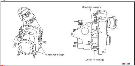
INSPECTION AFTER INSTALLATION
Start engine and raise engine speed to check no exhaust emission leaks.
 EGR valve
Exploded View
1. EGR valve assembly
2. Clamp
3. EGR tube
4. Air inlet tube
5. O-ring
6. Gasket
7. EGR cooler
8. Gasket
9. EGR volume control valve housing
10. Gasket
11. Electric t ...
 Exhaust manifold
Exploded View
1. Exhaust gas temperature sensor 1
2. Gasket
3. Exhaust manifold
4. Exhaust gas pressure sensor 1
A. To cylinder head
: N·m (kg-m, ft-lb)
: Always replace after every
disas ...
Other materials:
Precaution Necessary for Steering Wheel Rotation after Battery Dis
NOTE:
• Before removing and installing any control units, first turn the ignition
switch to the LOCK position, then disconnect
both battery cables.
• After finishing work, confirm that all control unit connectors are connected
properly, then re-connect both
battery cables.
• Always use CONS ...
Meter buzzer circuit
Component Function Check
1.CHECK OPERATION OF METER BUZZER
1. Select “BUZZER” of “BCM” on CONSULT-III.
2. Perform “LIGHT WARN ALM” of “Active Test”.
Does meter buzzer beep?
YES >> INSPECTION END
NO >> GO TO 2.
2.CHECK COMBINATION METER INPUT SIGNAL
Select the “Data Monitor” f ...
Cooling fan
Diagnosis Procedure
1.CHECK GROUND CONNECTION
1. Turn ignition switch OFF.
2. Check ground connection E38. Refer to Ground Inspection in GI-44, "Circuit
Inspection".
Is the inspection result normal?
YES >> GO TO 2.
NO >> Repair or replace ground connection.
2.CHE ...
