Nissan Juke Service and Repair Manual : Transaxle assembly
Exploded View
CASE AND HOUSING
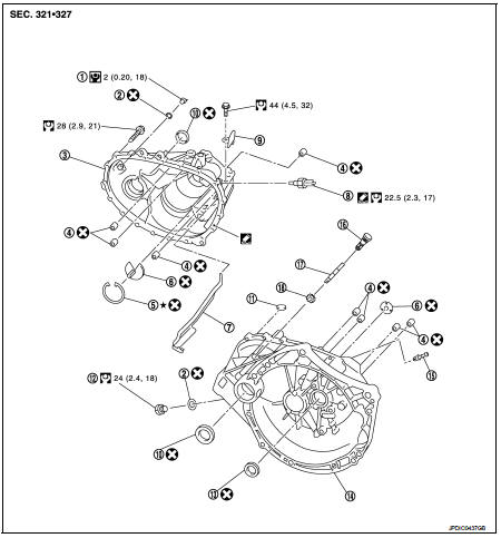
1. Filler plug
2. Gasket
3. Transaxle case
4. Bushing
5. Snap ring
6. Oil channel
7. Oil gutter
8. Position switch
9. Bracket
10. Differential side oil seal
11. Magnet
12. Drain plug
13. Input shaft oil seal
14. Clutch housing
15. 2 way connector
16. Plug
17. Pinion shaft
18. Pinion gear
 : Apply Genuine Liquid Gasket,
Three Bond 1215 or an equivalent.
 : Always replace after every
disassembly.
 : Select with proper thickness.
 : N·m (kg-m, ft-lb)
 : N·m (kg-m, in-lb)
SHAFT AND GEAR
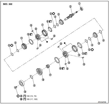
1. Input shaft front bearing
2. Input shaft
3. 3rd input gear
4. Spacer
5. Snap ring
6. 3rd baulk ring
7. 3rd-4th coupling sleeve
8. 3rd-4th synchronizer hub
9. Insert key
10. 4th baulk ring
11. 4th input gear
12. 5th input gear
13. 5th baulk ring
14. 5th-6th coupling sleeve
15. 5th-6th synchronizer hub
16. 6th baulk ring
17. Needle bearing
18. 6th input gear
19. Input shaft rear bearing
A. First step B. Final step
 : Apply gear oil.
 : Replace the parts as a set.
 : Always replace after every
disassembly.
 : N·m (kg-m, ft-lb)

1. Mainshaft front bearing outer
race
2. Mainshaft front bearing inner race
3. Mainshaft
4. 1st main gear
5. 1st inner baulk ring
6. 1st synchronizer cone
7. 1st outer baulk ring
8. 1st-2nd coupling sleeve
9. Insert key
10. 1st-2nd synchronizer hub
11. 2nd outer baulk ring
12. 2nd synchronizer cone
13. 2nd inner baulk ring
14. 2nd main gear
15. Bushing
16. 3rd main gear
17. Mainshaft adjusting shim
18. 4th main gear
19. 5th main gear
20. 6th main gear
21. Mainshaft rear bearing inner race
22. Mainshaft rear bearing outer race
23. Snap ring
24. Mainshaft rear bearing adjusting
shim
 : Apply gear oil.
 : Replace the parts as a set.
 : Select with proper thickness.
 : Always replace after every
disassembly
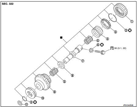
1. Reverse output gear 2. Snap ring 3. Reverse baulk ring 4. Return spring 5. Needle bearing 6. Seal washer 7. Reverse idler shaft 8. Spacer 9. Reverse input gear 10. Lock washer 11. Spring washer
 : Replace the parts as a set.
 : Always replace after every
disassembly.
 : N·m (kg-m, ft-lb)
SHIFT FORK AND FORK ROD
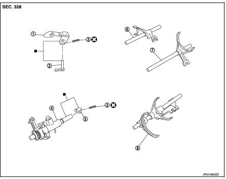
1. Shifter lever A 2. Shifter lever B 3. Retaining pin 4. Selector 5. Selector lever 6. Reverse fork rod 7. 1st-2nd fork rod 8. Fork rod
 : Replace the parts as a set.
 : Always replace after every
disassembly.
FINAL DRIVE
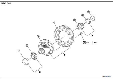
1. Shim
2. Differential side bearing outer race
(transaxle case side)
3. Differential side bearing inner race
(transaxle case side)
4. Final gear
5. Differential case
6. Differential side bearing inner race
(clutch housing side)
7. Differential side bearing outer race
(clutch housing side)
 : Replace the parts as a set.
 : N·m (kg-m, ft-lb)
Disassembly
1. Remove drain plug and gasket from clutch housing, using a socket [Commercial service tool] and then drain gear oil.
2. Remove filler plug and gasket from transaxle case.
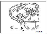
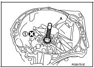
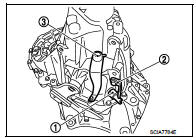
3. Remove selector lever (1) retaining pin with a pin punch to remove selector lever.
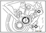
4. Remove bracket (2) and position switch (3) from transaxle case
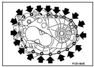
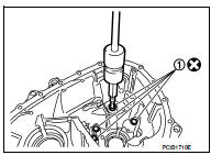
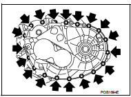
5. Remove transaxle case mounting bolts (
).
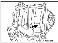
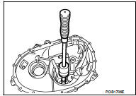
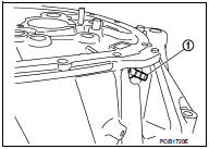
6. Remove reverse idler shaft mounting bolt (
 ) and seal washer.
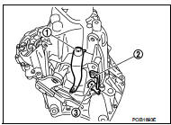
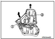
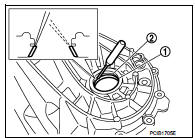
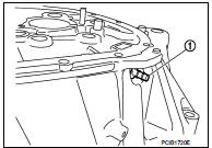
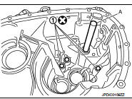
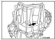
7. Remove transaxle case (2) while rotating shifter lever A (1) in the direction as shown in the figure.
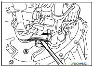
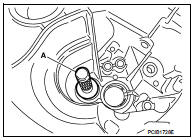
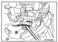
8. Remove selector spring (1) from return bushing (A).
9. Shift 1st-2nd fork rod (1), fork rod (2), and reverse fork rod (3) to the neutral position.
10. Remove selector (4) from clutch housing.
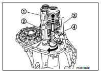
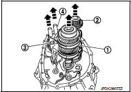
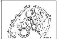
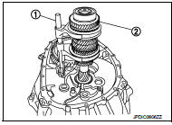
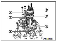
11. Remove reverse idler shaft assembly (1), as per the following procedure.
a. Pull up input shaft assembly (2), mainshaft assembly (3), fork rod (4), and 1st-2nd fork rod (5).
NOTE
:
It is easier to pull up when shifting each fork rod to each shaft
side.
b. Remove reverse idler shaft assembly and reverse fork rod (6) from clutch housing.
12. Remove spring washer from clutch housing.
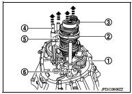
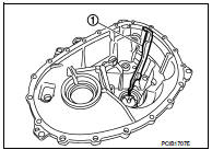
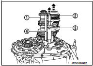
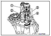
13. Pull up and remove input shaft assembly (1), mainshaft assembly (2), fork rod (3), and 1st-2nd fork rod (4) from clutch housing.
NOTE
:
It is easier to pull up when shifting each fork rod to each shaft
side.
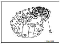
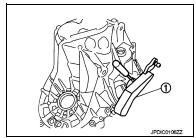
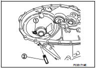
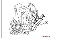
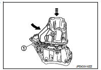
14. Remove final drive assembly (1) from clutch housing.
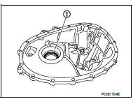
15. Remove magnet from clutch housing.
16. Remove differential side oil seals (1) from clutch housing and transaxle case.
CAUTION:
Never damage clutch housing and transaxle case.
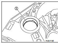
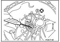
17. Remove differential side bearing outer race (1) from clutch housing, using a brass rod.
CAUTION:
Never damage clutch housing.
18. Remove differential side bearing outer race (1) from transaxle case, using a brass rod.
CAUTION:
Never damage transaxle case.
19. Remove shim (2) from transaxle case.
20. Remove shifter lever A (1) retaining pin, using a pin punch.
22. Remove shifter lever B (1) from transaxle case.
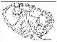
23. Remove oil gutter (1) from transaxle case.
24. Remove bushings (1) from transaxle case, using a remover [Commercial service tool].
25. Remove mainshaft rear bearing outer race from transaxle case, using a remover [Commercial service tool].
26. Remove mainshaft rear bearing adjusting shim from transaxle case.
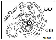
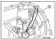
27. Remove snap ring (1) and oil channel (2) from transaxle case.
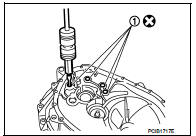
28. Remove input shaft oil seal (1) from clutch housing, using an oil seal remover.
CAUTION:
Never damage clutch housing.
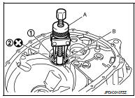
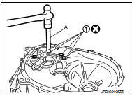
29. Remove mainshaft front bearing outer race (1) from clutch housing, using the puller (A) [SST: KV381054S0] and a spacer (B) [Commercial service tool].
30. Remove oil channel (2) from clutch housing.
31. Remove bushing (1) from clutch housing, using a remover [Commercial service tool].
32. Remove 2 way connector (1) from clutch housing.
33. Remove plug from clutch housing.
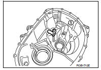
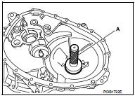
34. Remove pinion gear (1) and pinion shaft (2) from clutch housing.
Assembly
1. Install pinion gear (1) and pinion shaft (2) to clutch housing.
CAUTION:
Replace transaxle assembly when replacing clutch housing.
2. Install plug to clutch housing.
3. Install 2 way connector (1) to clutch housing.
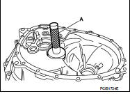
4. Install bushings (1) so that they becomes even to clutch housing edge surface, using a drift (A) [Commercial service tool].
5. Install oil channel to clutch housing.
CAUTION:
Never reuse oil channel.
6. Install mainshaft front bearing outer race to clutch housing, using the drift (A) [SST: KV38100200].
CAUTION:6. Install mainshaft front bearing outer race to clutch housing, using the drift (A) [SST: KV38100200].
CAUTION: Replace mainshaft front bearing outer race and mainshaft front bearing inner race as a set.
Replace mainshaft front bearing outer race and mainshaft front bearing inner race as a set.
7. Install input shaft oil seal (1) to clutch housing, using the drift (A) [SST: ST33220000].
8. Install snap ring (1) and oil channel (2) to transaxle case.
CAUTION:
• Select and install snap ring that has the same thickness
as previous one.
• Replace transaxle assembly when replacing transaxle case.
9. Install mainshaft rear bearing adjusting shim to transaxle case.
CAUTION:
Select mainshaft rear bearing adjusting shim, as per the following
procedure when replacing mainshaft adjusting
shim, 6th main gear, 5th main gear, or 4th main gear.
• Replace mainshaft adjusting shim.
- If new mainshaft adjusting shim is thinner than previous one, offset the thickness difference by selecting thicker mainshaft rear bearing adjusting shim.
- If new mainshaft adjusting shim is thicker than previous one, offset the thickness difference by selecting thinner mainshaft rear bearing adjusting shim.
• Replace 6th main gear, 5th main gear, or 4th main gear.
- Measure the thickness of the main gear used before and the new main gear - Increase the thickness of the mainshaft rear bearing adjusting shim, if the difference is smaller than 0.025 mm (0.0010 in).
- Decrease the thickness of the mainshaft rear bearing adjusting shim, if the difference is greater than 0.025 mm (0.0010 in
10. Install mainshaft rear bearing outer race to transaxle case, using the drift (A) [SST: KV38100200].
CAUTION:
Replace mainshaft rear bearing outer race and mainshaft
rear bearing inner race as a set.
11. Install bushings (1) to transaxle case, using a drift (A) [Commercial service tool].
12. Install oil gutter (1) to transaxle case.
13. Install shifter lever B (1) to transaxle case.
CAUTION:
Replace shifter lever A and shifter lever B as a set.
14. Install shifter lever A to transaxle case.
CAUTION:
Replace shifter lever A and shifter lever B as a set.
15. Install retaining pin to shifter lever A (1), using a pin punch.
CAUTION:
Never reuse retaining pin.
16. Install shim to transaxle case.
17. Install differential side bearing outer race (transaxle case side) to transaxle case, using the drift (A) [SST: ST33400001].
CAUTION:
Replace differential side bearing outer race (transaxle case
side) and differential side bearing inner race (transaxle case
side) as a set.
18. Install differential side bearing outer race (clutch housing side) to clutch housing, using the drift (A) [SST: KV38100200].
CAUTION:
Replace differential side bearing outer race (clutch housing
side) and differential side bearing inner race (clutch housing
side) as a set.
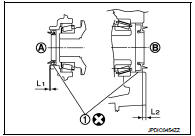
19. Install differential side oil seals (1) to clutch housing and transaxle case, using the drift [Stamping number: B.vi 1666-B] of the drift set [SST: KV32500QAA].
A : Transaxle case side B : Clutch housing side
Dimension “L1” : 1.2 – 1.8 mm (0.047 – 0.071 in) Dimension “L2” : 2.7 – 3.3 mm (0.106 – 0.130 in)
CAUTION:
• Never incline differential side oil seal.
• Never damage clutch housing and transaxle case.
20. Install magnet to clutch housing.
21. Install final drive assembly to clutch housing.
22. Set fork rod (1) to input shaft assembly (2), and then install them to clutch housing.
23. Install mainshaft assembly (1), as per the following procedure.
a. Pull up input shaft assembly (2) and fork rod (3).
b. Set 1st-2nd fork rod (4) to mainshaft assembly, and then install them to clutch housing.
24. Install reverse idler shaft assembly (1), as per the following procedure.
a. Install spring washer to clutch housing.
b. Pull up input shaft assembly (2), mainshaft assembly (3), fork rod (4), and 1st-2nd fork rod (5).
NOTE
:
It is easier to pull up when shifting each fork rod to each shaft
side.
c. Set reverse fork rod (6) to reverse idler shaft assembly, and then install them to clutch housing.
25. Shift 1st-2nd fork rod (1), fork rod (2), and reverse fork rod (3) to the neutral position.
26. Install selector (4) to clutch housing.
CAUTION:
Replace selector lever and selector as a set.
27. Install selector spring (1) to return bushing (A).
28. Apply recommended sealant to mounting surface of transaxle case.
• Use Genuine Liquid Gasket, Three Bond 1215 or an equivalent.
CAUTION:
• Never allow old liquid gasket, moisture, oil, or foreign
matter to remain on mounting surface.
• Check that mounting surface is not damaged.
• Apply sealant bead continuously.
29. Install transaxle case to clutch housing while rotating shifter lever A (1) in the direction as shown in the figure.
30. Install reverse idler shaft mounting bolt (
), as per the following
procedure.
a. Install seal washer to reverse idler shaft mounting bolt, and install reverse idler shaft mounting bolt to transaxle case.
CAUTION:
Never reuse seal washer.
b. Tighten reverse idler shaft mounting bolt to the specified torque.
31. Tighten transaxle case mounting bolts (
) to the specified
torque.
32. Install position switch (1), as per the following procedure.
a. Apply recommended sealant to threads of position switch.
• Use Genuine Liquid Gasket, Three Bond 1215 or an equivalent.
CAUTION:
Never allow old liquid gasket, moisture, oil, or foreign matter
to remain on thread.
b. Install position switch to transaxle case, and tighten it to the specified torque.
33. Install bracket (2) to transaxle case, and tighten mounting bolt to the specified torque.
34. Install selector lever (3), as per the following procedure.
a. Install selector lever to transaxle case.
CAUTION:
Replace selector lever and selector as a set.
b. Install retaining pin to selector lever, using a pin punch.
CAUTION:
Never reuse retaining pin.
35. Install drain plug, as per the following procedure.
a. Install gasket to drain plug.
CAUTION:
Never reuse gasket.
b. Install drain plug to clutch housing, using a socket [Commercial service tool].
c. Tighten drain plug to the specified torque.
36. Install filler plug, as per the following procedure.
a. Install gasket to filler plug, and then install them to transaxle case.
CAUTION:
Never reuse gasket.
b. Tighten filler plug to the specified torque.
CAUTION:
Fill with gear oil before tighten filler plug to the specified torque.
Inspection
INSPECTION AFTER DISASSEMBLY
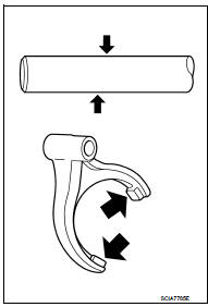
Check contact surface and sliding surface for excessive wear, uneven wear, bend, and damage. Replace if necessary.

 Input shaft and gear
Exploded View
1. Input shaft front bearing
2. Input shaft
3. 3rd input gear
4. Spacer
5. Snap ring
6. 3rd baulk ring
7. 3rd-4th coupling sleeve
8. 3rd-4th synchronizer hub
9. Insert k ...
Other materials:
Turbocharger boost control
Turbocharger boost control : SystemDiagram
Turbocharger boost control : System Description
INPUT/OUTPUT SIGNAL CHART
SYSTEM DESCRIPTION
Depending on driving conditions, the ECM performs ON/OFF duty control of the
turbocharger boost control
solenoid valve and controls the boost by adjustin ...
Component parts
Component Parts Location
1. Remote keyless entry receiver
Refer to DLK-361,
"Component Parts Location" (With
super lock) or DLK-492,
"Component Parts Location" (Without
super lock).
2. Combination meter
Refer to MWI-4, "METER SYSTEM :
Component Parts Location" ...
Air breather hose
Removal and Installation
REMOVAL
1. Remove clip from bracket.
2. Remove air breather hose from transaxle assembly.
INSTALLATION
Note the following, and install in the reverse order of removal.
CAUTION:
• Check that air breather hose is not collapsed or blocked due to folding or
bending ...
