Nissan Juke Service and Repair Manual : Transaxle assembly
Exploded View
CASE AND HOUSING
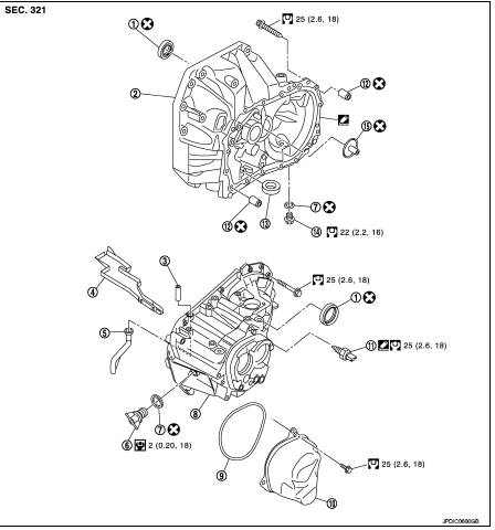
1. Differential side oil seal
2. Clutch housing
3. 2 way connector
4. Oil gutter
5. Air breather inner tube
6. Filler plug
7. Gasket
8. Transaxle case
9. O-ring
10. Rear housing
11. Position switch
12. Dowel pin
13. Magnet
14. Drain plug
15. Oil channel
 : Apply Genuine Liquid Gasket,
Three Bond 1215 or an equivalent.
 : Always replace after every
disassembly.
 : N·m (kg-m, ft-lb)
 : N·m (kg-m, in-lb)
SHAFT AND GEAR
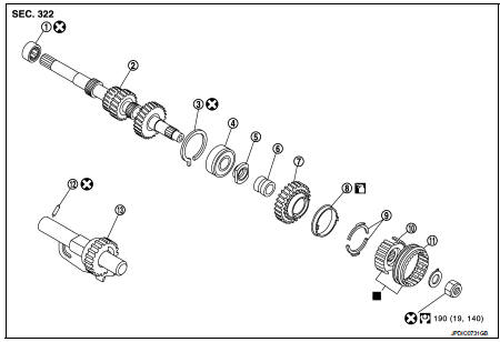
1. Input shaft front bearing
2. Input shaft
3. Snap ring
4. Input shaft rear bearing
5. Adapter plate
6. Bushing
7. 5th input gear
8. 5th-reverse baulk ring
9. Synchronizer lever
10. 5th-reverse synchronizer hub
11. 5th-reverse coupling sleeve
12. Retaining pin
13. Reverse gear
 : Apply gear oil.
 : Replace the parts as a set.
: Always replace after every
disassembly.
 : N·m (kg-m, ft-lb)
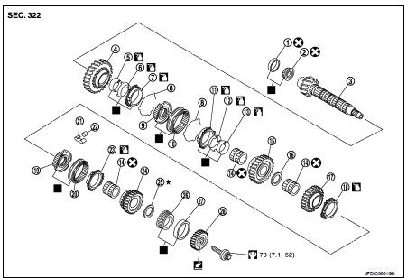
1. Mainshaft front bearing outer
race
2. Mainshaft front bearing inner race
3. Mainshaft
4. 1st main gear
5. 1st inner baulk ring
6. 1st synchronizer cone
7. 1st outer baulk ring
8. Spread spring
9. 1st-2nd synchronizer hub
10. 1st-2nd coupling sleeve
11. 2nd outer baulk ring
12. 2nd synchronizer cone
13. 2nd inner baulk ring
14. Mainshaft bushing
15. 2nd main gear
16. Thrust washer
17. 3rd main gear
18. 3rd baulk ring
19. 3rd-4th synchronizer hub
20. 3rd-4th coupling sleeve
21. Spring
22. Insert key
23. 4th baulk ring
24. 4th main gear
25. Adjusting shim
26. Mainshaft rear bearing inner race
27. Mainshaft rear bearing outer race
28. 5th main gear
: Apply gear oil.
 : Apply Thread Locking Sealant,
Loctite Frenbloc or an equivalent.
 : Replace the parts as a set.
 : Always replace after every
disassembly.
 : Select with proper thickness.
: N·m (kg-m, ft-lb)
SHIFT FORK AND FORK ROD
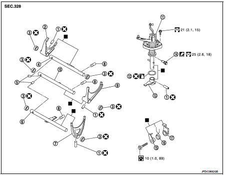
1. Retaining pin
2. 1st-2nd shift fork
3. Bushing
4. 1st-2nd fork rod
5. Lock pin
6. 5th-reverse fork rod
7. 5th-reverse shift fork
8. Check ball
9. 3rd-4th shift fork
10. 3rd-4th fork rod
11. Control shaft
12. O-ring
13. Selector
14. Check ball plug
15. Bushing
16. Spring
17. Gear catch
 : Apply gear oil.
 : Apply Genuine Liquid Gasket,
Three Bond 1215 or an equivalent.
 : Replace the parts as a set.
 : Always replace after every
disassembly.
 : N·m (kg-m, ft-lb)
 : N·m (kg-m, in-lb)
FINAL DRIVE
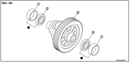
1. Differential side bearing outer race
2. Differential side bearing
3. Final drive
 : Replace the parts as a set.
Disassembly
1. Remove drain plug and gasket from clutch housing, using a socket [Commercial service tool] and drain gear oil.
2. Remove filler plug and gasket from transaxle case.
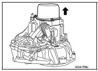
3. Remove rear housing and O-ring.
CAUTION:
Remove to axial direction of input shaft (
 ) because rear
housing oil channel is inserted to input shaft center hole
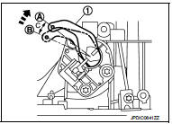
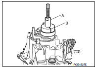
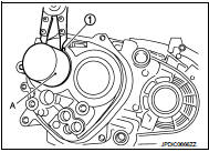
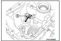
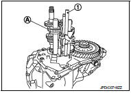
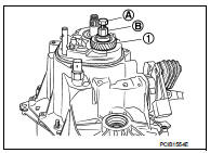
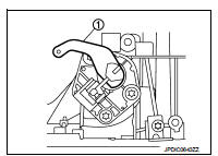
4. Shift the shifter lever A (1) to the 3rd gear position (A).
B : Neutral position
C : Approx. 15 degrees
NOTE
:
• If it is not shifted to the 3rd gear position, transaxle case cannot
be removed from clutch housing.
• Shifter lever A is set in the 3rd gear position by turning in the direction indicated by arrow.
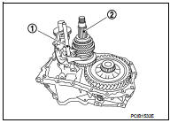
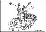
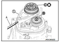
5. Remove 5th-reverse shift fork (1) and 5th-reverse coupling sleeve, as per the following procedure.
a. Remove retaining pin from 5th-reverse shift fork, using a pin punch (A).
b. Press 5th-reverse shift fork, shift to 5th, and then engage it with 3rd gear.
c. Remove mounting bolt (B).
d. Remove mounting nut (C) and washer.
CAUTION:
Never use an impact wrench for removal, or otherwise each
gear may be damaged.
e. Remove 5th-reverse shift fork and 5th-reverse coupling sleeve from 5th-reverse synchronizer hub.
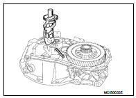
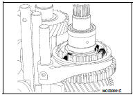
6. Remove 5th-reverse synchronizer hub from input shaft, using a puller [Commercial service tool].
CAUTION:
Set claw of the puller to the wider side of the hub when setting
the puller in 5th-reverse synchronizer hub.
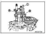
7. Remove synchronizer levers, 5th-reverse baulk ring, 5th input gear, bushing, and adapter plate from input shaft.
8. Remove 5th main gear from mainshaft, using the pullers.
A : Puller [SST: KV32300QAC] B : Puller [SST: KV32300QAD]
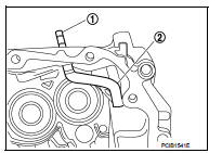
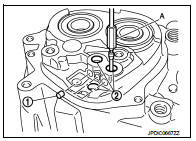
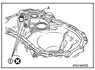
9. Remove position switch from transaxle case.
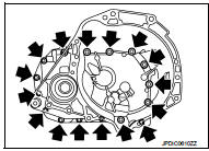
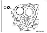
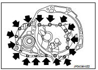
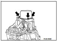
10. Remove transaxle case mounting bolts (
 ).
).
11. Remove transaxle case from clutch housing.
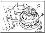
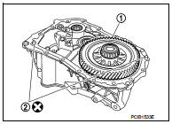
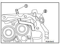
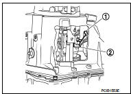
12. Remove mainshaft rear bearing inner race (1), adjusting shim, and 4th main gear (2) from mainshaft.
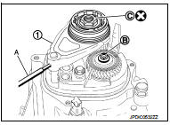
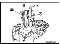
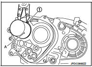
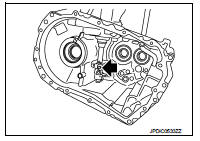
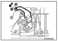
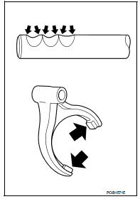
13. Remove 5th-reverse fork rod (1), as per the following procedure.
a. Pull 5th-reverse fork rod up until it contacts claw (A) of reverse gear.
b. Press gear portion (B) of reverse gear down, and then remove 5th-reverse fork rod from clutch housing.
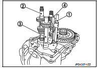
14. Remove 3rd-4th fork rod assembly (1), 3rd-4th coupling sleeve, and input shaft (2), as per the following procedure.
a. Remove 4th baulk ring, insert keys, and springs from mainshaft.
b. Pull gear of reverse gear (3) up.
c. Pull 1st-2nd fork rod (4) up, and then maintain the neutral position.
d. Remove 3rd-4th fork rod assembly, 3rd-4th coupling sleeve, and input shaft from clutch housing at the same time.
15. Remove retaining pin from 3rd-4th shift fork, using a pin punch.
16. Remove 3rd-4th shift fork from 3rd-4th shift fork rod.
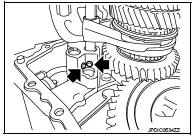
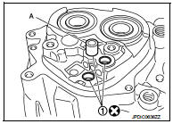
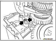
17. Remove lock pins (  ) from
clutch housing.
18. Remove 1st-2nd fork rod assembly (1) and mainshaft assembly (2) from clutch housing at the same time.
19. Remove retaining pin from 1st-2nd shift fork, using a pin punch.
20. Remove 1st-2nd shift fork from 1st-2nd shift fork rod.
21. Remove retaining pin from reverse gear, using a pin punch.
22. Remove reverse gear from clutch housing.
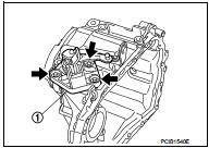
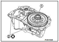
23. Remove final drive (1) from clutch housing.
24. Remove magnet and dowel pins (2) from clutch housing.
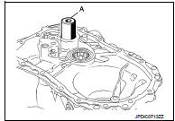
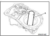
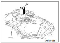
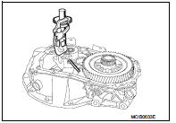
25. Remove input shaft front bearing from clutch housing, using a drift (A) [Commercial service tool].
26. Cut oil channel tube at the root.
27. Remove mainshaft front bearing outer race from clutch housing, using a remover [Commercial service tool].
28. Remove oil channel from clutch housing.
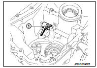
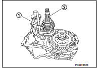
29. Remove bushings (1) from clutch housing, using a remover [Commercial service tool].
30. Remove differential side oil seals (1) from clutch housing and transaxle case, using an oil seal remover.
CAUTION:
Never damage transaxle case and clutch housing.
31. Remove differential side bearing outer races (1) from clutch housing and transaxle case, using a brass rod.
CAUTION:
Never damage transaxle case and clutch housing.
32. Pull 2 way connector (1) straight to remove it from air breather inner tube (2).
33. Remove air breather inner tube from transaxle case.
34. Remove oil gutter from transaxle case.
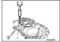
35. Remove retaining pin (1) from selector, using a pin punch.
36. Remove mounting bolt ( ),
),
and then remove bushing, spring,
and gear catch from transaxle case.
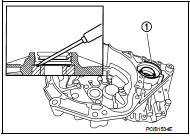
37. Remove check ball plug from transaxle case.
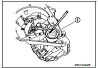
38. Remove mounting bolts (  ),
),
and then remove control shaft (1)
and selector from transaxle case.
39. Remove O-ring from control shaft.
40. Remove check balls (1) from transaxle case.
41. Remove bushings (2) from transaxle case, using a remover (A) [Commercial service tool].
42. Expand snap ring (1) and remove input shaft rear bearing from transaxle case, using a drift (A) [Commercial service tool].
43. Remove snap ring from transaxle case.
44. Remove mainshaft rear bearing outer race from transaxle case, using a drift (A) [Commercial service tool].
Assembly
1. Install mainshaft rear bearing outer race to transaxle case, using a drift [Commercial service tool].
CAUTION:
Replace mainshaft rear bearing outer race and mainshaft
rear bearing inner race as a set.
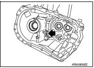
2. Install snap ring (1) along transaxle case groove so that notch
mates with housing as shown in the figure.
CAUTION:
Check snap ring installing direction. Never misassemble.
3. Expand snap ring (1) and install input shaft rear bearing to transaxle case, using a drift (A) [Commercial service tool].
CAUTION:
Check that snap ring is correctly installed within bearing
groove.
4. Install bushings (1) until they reach transaxle case, using a drift (A) [Commercial service tool].
5. Install check balls to transaxle case.
6. Apply gear oil to O-ring, and then install it to control shaft.
CAUTION:
Never reuse O-ring.
7. Install control shaft (1) and selector to transaxle case, and
tighten mounting bolts (  ) to the
specified torque.
CAUTION:
• Replace control shaft and selector as a set.
• Be careful with the orientation of selector.
8. Install retaining pin (1) to selector, using a pin punch.
CAUTION:
Never reuse retaining pin.
9. Install gear catch, spring, and bushing to transaxle case, and
then tighten mounting bolt ( ) to
) to
the specified torque.
CAUTION:
Replace gear catch, spring, and bushing as a set.
10. Install oil gutter to transaxle case.
11. Install air breather inner tube (2) to transaxle case.
CAUTION:
Never damage air breather inner tube.
NOTE
:
It is easier to install when air breather inner tube end is wrapped
and narrowed by tape. Remove tape after installation.
12. Insert 2 way connector (1) straight, and then install it to air breather inner tube.
CAUTION:
Check air breather inner tube for twists after installing.
13. Install differential side bearing outer races until they reach clutch housing and transaxle case, using a drift (A) [Commercial service tool].
CAUTION:
Replace differential side bearing outer race and differential
side bearing as a set.
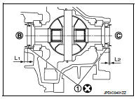
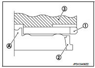
14. Install differential side oil seals (1) to clutch housing and transaxle case, using the drift [Stamping number: B.vi 1666-B] of the drift set [SST: KV32500QAA].
B : Transaxle case side C : Clutch housing side
Dimension “L1” : 5.7 – 6.3 mm (0.224 – 0.248 in) Dimension “L2” : 2.4 – 3.0 mm (0.094 – 0.118 in)
CAUTION:
• Never incline differential side oil seal.
• Never damage clutch housing and transaxle case.
15. Install bushings (1) until they reach clutch housing, using a drift (A) [Commercial service tool].
16. Install oil channel to clutch housing.
CAUTION:
Never reuse oil channel.
17. Install mainshaft front bearing outer race until they reach clutch housing, using a drift [Commercial service tool].
CAUTION:
• Never reuse mainshaft front bearing outer race.
• Replace mainshaft front bearing outer race and mainshaft front bearing inner race as a set.
18. Install input shaft front bearing so that it becomes even to clutch housing surface, using a drift (A) [Commercial service tool].
CAUTION:
Never reuse input shaft front bearing.
19. Install final drive (1) to clutch housing.
20. Install dowel pins (2) and magnet to clutch housing.
21. Install reverse gear to clutch housing, and then install retaining pin to clutch housing, using a pin punch.
CAUTION:
Never reuse retaining pin.
22. Install 1st-2nd shift fork to 1st-2nd fork rod, and then install retaining pin to 1st-2nd shift fork.
CAUTION:
• Never reuse retaining pin.
• Replace 1st-2nd fork rod and 1st-2nd shift fork as a set.
23. Set 1st-2nd fork rod assembly (1) onto mainshaft assembly (2), and then install them to clutch housing.
24. Install lock pins ( ) to
) to
clutch housing.
25. Install 3rd-4th shift fork to 3rd-4th fork rod, and then install retaining pin to 3rd-4th shift fork.
CAUTION:
• Never reuse retaining pin.
• Replace 3rd-4th fork rod and 3rd-4th shift fork as a set.
26. Install 3rd-4th fork rod assembly (1), 3rd-4th coupling sleeve, and input shaft (2) to clutch housing, as per the following procedure.
a. Pull 1st-2nd fork rod (3) up, and then maintain the neutral position.
b. Set 3rd-4th fork rod assembly onto 3rd-4th coupling sleeve, and then install them together with input shaft to clutch housing.
CAUTION:
• Set lock pin (3rd-4th fork rod side) onto 1st-2nd fork rod
groove and then install 3rd-4th fork rod assembly.
• Be careful with the orientation of 3rd-4th coupling sleeve.
A : 4th main gear side B : 3rd main gear side
• Install 3rd input gear of input shaft so that it is set under reverse main gear of 3rd-4th coupling sleeve.
• Replace 3rd-4th coupling sleeve and 3rd-4th synchronizer hub as a set.
c. Install springs and insert keys to 3rd-4th synchronizer hub.
d. Apply gear oil to 4th baulk ring.
e. Install 4th baulk ring.
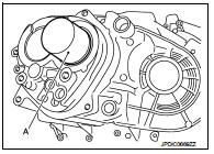
27. Install 5th-reverse fork rod (1) to clutch housing, as per the following procedure.
CAUTION:
Replace 5th-reverse fork rod and 5th-reverse shift fork as a
set.
a. Pull gear (A) of reverse gear up.
b. Temporarily install 5th-reverse fork rod to clutch housing.
c. Press gear (A) of reverse gear down and then install 5th-reverse fork rod (1) to clutch housing.
CAUTION:
Set levers of 5th-reverse fork rod so as to align with reverse
gear groove (B).
28. Install 4th main gear to mainshaft.
29. Install adjusting shim to mainshaft.
CAUTION:
After replacing the following parts, adjust mainshaft rear bearing preload to
install a selected
adjusting shim to the mainshaft.
• Mainshaft
• Mainshaft front bearing inner race
• Mainshaft front bearing outer race
• Mainshaft rear bearing inner race
• Mainshaft rear bearing outer race
• Clutch housing
• Transaxle case
30. Install mainshaft rear bearing inner race to mainshaft.
CAUTION:
Replace mainshaft rear bearing inner race and mainshaft rear bearing outer race
as a set.
31. Press 3rd-4th shift fork down and then shift 3rd-4th coupling sleeve to 3rd gear side.
32. Turn the shifter lever A (1) fully clockwise to position (A) and move back the lever 10 degrees to position (B).
NOTE
:
This position allows the transaxle case to be properly installed to
the clutch housing.
33. Apply recommended sealant to transaxle case mounting surface of clutch housing.
• Use Genuine Liquid Gasket, Three Bond 1215 or an equivalent.
CAUTION:
• Never allow old liquid gasket, moisture, oil, or foreign
matter to remain on mounting surface.
• Check that mounting surface is not damaged.
• Apply a continuous bead of liquid gasket to the mounting surface.
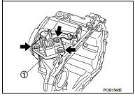
34. Install transaxle case to clutch housing. If it is difficult to install, slightly rotate shifter lever A counterclockwise, and then install.
1 : Selector
2 : Shift fork
CAUTION:
• Never disrupt liquid gasket bead with transaxle case or
other objects during installation.
• Be careful to align the lever of 5th-reverse fork rod with reverse gear groove.
35. Rotate input shaft so that bearing and shaft fit each other, and
then tighten transaxle mounting bolts (
) to the specified
torque.
36. Apply recommended sealant to position switch thread and check ball plug thread. Tighten them to transaxle case and them to the specified torque.
• Use Genuine Liquid Gasket, Three Bond 1215 or an equivalent.
CAUTION:
Never allow old liquid gasket, moisture, oil, or foreign matter
to remain on thread.
37. Apply thread locking sealant to 5th main gear spline.
• Use Thread Locking Sealant, Loctite Frenbloc or an equivalent.
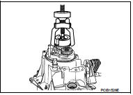
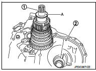
38. Install 5th main gear (1) to mainshaft, using a suitable bolt (A) [M10 x 1.0] and a suitable nut (B).
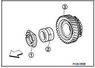
39. Install adapter plate (1), bushing (2), and 5th input gear (3) to input shaft.
 : Transaxle case side
CAUTION:
Be careful with the orientation of adapter plate.
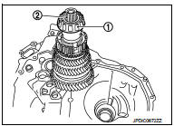
40. Apply gear oil to 5th-reverse baulk ring (1).
41. Install 5th-reverse baulk ring, synchronizer levers (2), and 5threverse synchronizer hub (3) to 5th input gear.
 : 5th-reverse synchronizer hub
side
CAUTION:
• Be careful with the orientation of 5th-reverse baulk ring.
• Replace 5th-reverse synchronizer hub and 5th-reverse coupling sleeve as a set.
• Be careful with the orientation of synchronizer lever.
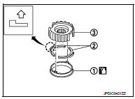
• Be careful with the orientation of 5th-reverse synchronizer hub.
 : 5th input gear side
• Never allow synchronizer lever (1) to mount on to 5threverse baulk ring (2) protrusion (A).
3 : 5th-reverse synchronizer hub
42. Install washer to input shaft.
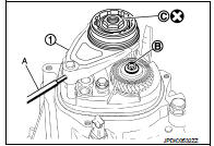
43. Set 5th-reverse shift fork (1) to 5th-reverse coupling sleeve, and then install them to 5th-reverse fork rod and input shaft.
A : Pin punch
B : Mounting bolt
C : Mounting nut
CAUTION:
• Be careful with the orientation of 5th-reverse coupling
sleeve.
: 5th input gear side
• Replace 5th-reverse synchronizer hub and 5th-reverse coupling sleeve as a set.
• Replace 5th-reverse shift fork and 5th-reverse fork rod as a set.
44. Check that the gear position is in the 3rd gear position. Press 5th-reverse shift fork and shift to 5th gear.
45. Tighten mounting bolt (B) to the specified torque.
46. Tighten mounting nut (C) to the specified torque.
47. Install retaining pin to 5th-reverse shift fork (1), using a pin punch (A).
CAUTION:
Never reuse retaining pin.
48. Shift the shifter lever A (1) to the neutral position.
49. Install O-ring to rear housing.
50. Install rear housing to transaxle case, and tighten bolts (
) to
the specified torque.
CAUTION:
Never pinch O-ring when installing rear housing.
51. Install drain plug, as per the following procedure.
a. Install gasket to drain plug.
CAUTION:
Never reuse gasket.
b. Install drain plug to clutch housing, using a socket [Commercial service tool].
c. Tighten drain plug to the specified torque.
52. Install filler plug, as per the following procedure.
a. Install gasket to filler plug, and then install them to transaxle case.
CAUTION:
Never reuse gasket.
b. Tighten filler plug to the specified torque.
CAUTION:
Fill with gear oil before tightening filler plug to the specified torque.
Inspection and Adjustment
INSPECTION AFTER DISASSEMBLY
Check contact surface and sliding surface for excessive wear, uneven wear, bend, and damage. Replace if necessary.
ADJUSTMENT
Mainshaft Rear Bearing Preload NOTE
:
An adequate adjusting shim must be selected after replacing mainshaft, mainshaft
front bearing inner race,
mainshaft front bearing outer race, mainshaft rear bearing inner race, mainshaft
rear bearing outer race, clutch
housing, or transaxle case.
1. Install mainshaft assembly to clutch housing, as per the following procedure.
a. Install oil channel to clutch housing.
CAUTION:
Never reuse oil channel.
b. Install mainshaft front bearing outer race to clutch housing, using a drift [Commercial service tool].
CAUTION:
• Never reuse mainshaft front bearing outer race.
• Replace mainshaft front bearing outer race and mainshaft front bearing inner race as a set.
c. Install mainshaft front bearing inner race to mainshaft, using a drift [Commercial service tool].
CAUTION:
• Never reuse mainshaft front bearing inner race.
• Replace mainshaft front bearing inner race and mainshaft front bearing outer race as a set.
d. Install mainshaft assembly (1) to clutch housing (2).
e. Install the dummy shim [1.60 mm (0.0630 in) thickness] (A) of dummy shim set [SST: KV32300QAN] to the mainshaft.
f. Install mainshaft rear bearing inner race (1) to mainshaft (2).
CAUTION:
Replace mainshaft rear bearing inner race and mainshaft
rear bearing outer race as a set.
2. Install mainshaft rear bearing outer race to transaxle case, using a drift [Commercial service tool].
CAUTION:
Replace mainshaft rear bearing inner race and mainshaft
rear bearing outer race as a set.
3. Install transaxle case to clutch housing and then tighten mounting
bolts ( ) to the specified torque.
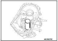
![4. Install adjusting plate (A) [SST: KV32300QAP], suitable washer,](images/books/335/25/index266.jpg)
4. Install adjusting plate (A) [SST: KV32300QAP], suitable washer, and suitable bolt (C) [M10 x 1.0] to mainshaft.
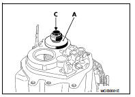
5. Install dial indicator to the transaxle case.
6. After rotating the mainshaft several turns for conforming the bearing, bring the dial indicator meter to zero.
7. Pull up the mainshaft, using two suitable tools.
8. Read the meter on the dial indicator.
9. Repeat Step 6 to 8 three times and calculate the average value of the readings.
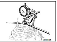
10. Calculate and select the thickness of adjusting shim.
Specified value [0.26 mm (0.0102 in)] + Dummy shim [1.60 mm (0.0630 in)] + Average value of dial indicator readings = Adjusting shim thickness

NOTE
:
Adjusting shim is configured for a thickness between 2.15 mm (0.0846 in) and
2.43 mm (0.0957 in) [0.04
mm (0.0016 in) intervals].

 Input shaft and gear
Exploded View
1. Input shaft front bearing
2. Input shaft
3. Snap ring
4. Input shaft rear bearing
5. Adapter plate
6. Bushing
7. 5th input gear
8. 5th-reverse baulk ring
9. Synchroni ...
Other materials:
Compressor dose dot operate
Description
SYMPTOM
Compressor dose not operate.
Diagnosis Procedure
NOTE:
• Perform self-diagnosis with CONSULT-III before performing symptom diagnosis.
If any malfunction result or
DTC is detected, perform the corresponding diagnosis.
• Check that refrigerant is enclosed in cooler cycle n ...
Glass
Use glass cleaner to remove smoke and dust film from the glass surfaces. It is
normal for glass to become coated with a film after the vehicle is parked in the
hot sun. Glass cleaner and a soft cloth will easily remove this film.
CAUTION
When cleaning the inside of the windows, do not use shar ...
Water hose
Exploded View
1. Hose clamp
2. Water hose
A. Water outlet
B. Oil warm
Removal and Installation
REMOVAL
WARNING:
Never remove the radiator cap when the engine is hot. Serious burns could occur
from high pressure
coolant escaping from the radiator.
CAUTION:
Perform these steps after t ...
