Nissan Juke Service and Repair Manual : Timing chain
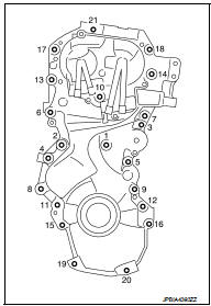
Exploded View
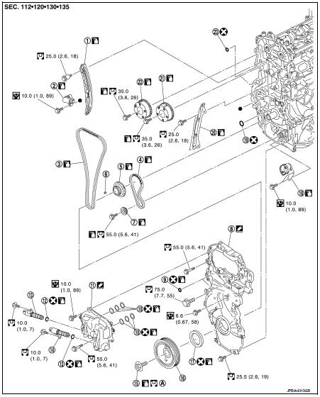
1. Timing chain slack guide
2. Timing chain tensioner
3. Timing chain
4. Oil pump drive chain
5. Crankshaft sprocket
6. Crankshaft key
7. Oil pump sprocket
8. Front cover
9. O-ring
10. O-ring
11. Oil control valve cover
12. O-ring
13. Oil control valve (EXH)
14. Oil control valve (INT)
15. Crankshaft pulley bolt
16. Crankshaft pulley
17. Front oil seal
18. Oil pump drive chain tensioner
19. O-ring
20. Timing chain tension guide
21. Camshaft spsocket (INT)
22. Camshaft sprocket (EXH)
23. O-ring
A.Tightening must be done following the installation procedure.
Refer to EM-68
 : N·m (kg-m, ft-lb)
 : N·m (kg-m, in-lb)
 : Always replace after every
disassembly.
 : Should be lubricated with oil.
 : Sealing point
Removal and Installation
REMOVAL
CAUTION:
The rotating direction in the text indicates all directions seen from the engine
front.
1. Drain engine oil. Refer to LU-9, "Draining".
CAUTION:
Perform this step when engine is cold.
2. Remove the following parts: • Intake manifold: Refer to EM-28, "Exploded View".
• Rocker cover: Refer to EM-23, "Exploded View".
3. Set No. 1 cylinder at TDC on its compression stroke with the following
procedure:
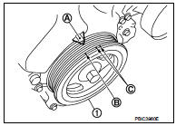
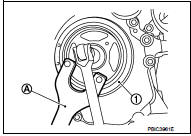
a. Rotate crankshaft pulley (1) clockwise and align TDC mark (no
paint) (B) to timing indicator (A) on front cover.
C : White paint mark (Not use for service)
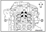
b. At the same time, check that the cam noses of the No. 1 cylinder
are located (  ) as shown in the
figure.
1 : Camshaft (INT)
2 : Camshaft (EXH)
 : Engine front
• If not, rotate crankshaft pulley one revolution (360 degrees) and align as shown in the figure.
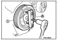
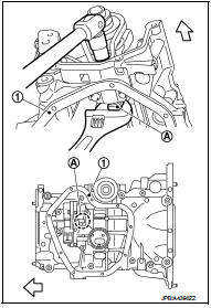
4. Remove crankshaft pulley with the following procedure:
a. Fix crankshaft pulley (1) with a pulley holder (commercial service tool) (A), loosen crankshaft pulley bolt, and locate bolt seating surface at 10 mm (0.39 in) from its original position.
CAUTION:
Never remove the crankshaft pulley bolt as they will be
used as a supporting point for the pulley puller [SST:
KV11103000 ( — )].
![b. Attach a pulley puller [SST: KV11103000 ( — )] (A) in the M6](images/books/335/2/index.96.jpg)
b. Attach a pulley puller [SST: KV11103000 ( — )] (A) in the M6 thread hole on crankshaft pulley (1), and remove crankshaft pulley.
5. Remove oil pan (lower). Refer to EM-99, "Exploded View".
NOTE
:
If crankshaft sprocket and oil pump drive component are not removed, this step
is unnecessary.
6. Remove intake valve timing control solenoid valve.
7. Remove drive belt auto-tensioner. Refer to EM-66, "Exploded View".
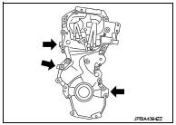
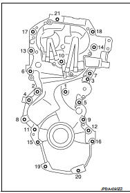
8. Remove front cover with the following procedure: a. Loosen mounting bolts in reverse order as shown in the figure.
b. Cut liquid gasket by prying the position (
) shown in the figure,
and then remove the front cover.
CAUTION:
• Be careful not to damage the mating surface.
• A more adhesive liquid gasket is applied compared to previous types when shipped, so it should not be forced off the position not specified.
9. Remove front oil seal from front cover.
CAUTION:
Be careful not to damage front cover.
• Lift up front oil seal using a screwdriver.
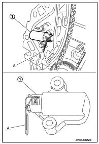
10. Remove timing chain tensioner with the following procedure: a. Insert a wire (A) (e.g. clip) into the top groove with the timing chain tensioner plunger pressed.
NOTE:
Timing chain tensioner plunger is securely fixed by inserting a
wire (e.g. clip).
b. Remove timing chain tensioner (1).
11. Remove slack guide (2), tension guide (3) and timing chain (1).
CAUTION:
Never rotate each crankshaft and camshaft individually
while timing chain is removed. It causes interference
between valve and piston.
NOTE:
If timing chain is difficult to remove, remove camshaft sprocket (EXH) first to remove timing chain.
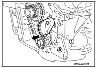
12. Remove crankshaft sprocket and oil pump drive component with the following procedure: a. Push oil pump drive chain tensioner (1) in the direction show in the figure (A).
b. Insert a stopper pin (A) into the body hole (B).
c. Remove oil pump chain tensioner.
• When the holes on lever and tensioner body cannot be alirned, align these holes by slightly moving the oil pump chain tensioner slack guide.
![d. Hold the WAF part of oil pump shaft [WAF: 10 mm (0.39 in)] (A),](images/books/335/2/index.104.jpg)
d. Hold the WAF part of oil pump shaft [WAF: 10 mm (0.39 in)] (A), and then loosen the oil pump sprocket bolt and remove it.
1 : Oil pan (upper)
 : Engine front
CAUTION:
• Secure the oil pump shaft with the WAF part.
• Never loosen the oil pump sprocket bolt by tightening the oil pump drive chain.
13. Remove tension guide (front cover side) from front cover, if necessary.
INSTALLATION
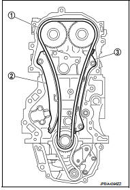
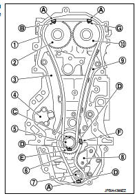
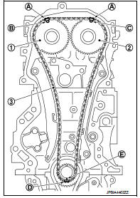
NOTE
:
The figure shows the relationship between the matching mark on
each timing chain and that on the corresponding sprocket, with the
components installed.
1 : Timing chain
2 : Camshaft sprocket (EXH)
3 : Slack guide
4 : Timing chain tensioner
5 : Crankshaft sprocket
6 : Oil pump drive chain
7 : Oil pump sprocket
8 : Oil pump drive chain tensioner
9 : Tension guide
10 : Camshaft sprocket (INT)
A : Matching mark (dark blue link) B : Matching mark (outer groove*) C : Crankshaft key position (straight up) D : Matching mark (stamping) E : Matching mark (white link) F : Matching mark (yellow link) G : Matching mark (outer groove)
*: There are two outer grooves in camshaft sprocket (EXH). The wider one is a matching mark.
1. Check that crankshaft key points straight up.
2. If the tension guide (front cover side) is removed, install it to the front cover.
CAUTION:
Check the joint condition by sound or feeling.
3. Install crankshaft sprocket (2), oil pump sprocket (3), and oil pump drive chain (1).
A : Matching mark (stamping) B : Matching mark (yellow link) C : Matching mark (dark blue link)
• Install it by aligning matching marks on each sprockets and oil pump drive chain.
• If these matching marks are not aligned, rotate the oil pump shaft slightly to correct the position.
CAUTION:
Check matching mark position of each sprockets after
installing the oil pump drive chain.
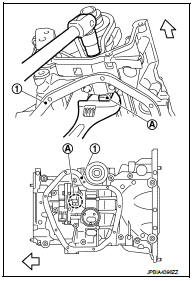
![4. Hold the WAF part of oil pump shaft [WAF: 10 mm (0.39 in)] (A),](images/books/335/2/index.107.jpg)
4. Hold the WAF part of oil pump shaft [WAF: 10 mm (0.39 in)] (A), and then tighten the oil pump shaft sprocket bolt.
1 : Oil pan (upper)
 : Engine front
CAUTION:
• Secure the oil pump shaft with the WAF part.
• Never loosen the oil pump shaft sprocket bolt by tightening the oil pump drive chain.
5. Install oil pump chain tensioner (1).
• Fix the plunger at the most compressed position using a stopper pin (A), and then install it.
• Securely pull out ( ) the stopper
pin after installing the oil
pump chain tensioner.
• Check matching mark position of oil pump drive chain and each sprockets again.
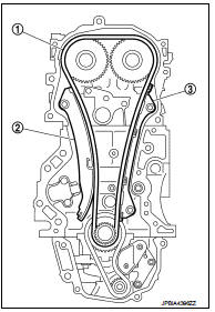
6. Align the matching marks of each sprockets with the matching marks of timing chain.
1 : Camshaft sprocket (EXH) 2 : Camshaft sprocket (INT) 3 : Timing chain
A : Matching mark (dark blue link) B : Matching mark (outer groove*) C : Matching mark (outer groove) D : Matching mark (white link) E : Matching mark (stamping)
*: There are 2 outer grooves in camshaft sprocket (EXH). The wider one is a matching mark.
• If these matching marks are not aligned, rotate the camshaft slightly by holding the hexagonal portion to correct the position.
CAUTION:
Check matching mark position of each sprocket and timing
chain again after installing the timing chain.
7. Install the slack guide (2) and the tension guide (3).
1 : Timing chain
8. Install timing chain tensioner.
• Fix the plunger at the most compressed position using a stopper pin, and then install it.
• Securely pull out the stopper pin after installing the timing chain tensioner.
9. Check matching mark position of timing chain and each sprockets again.
10. Install front oil seal. Refer to EM-88, "FRONT OIL SEAL : Removal and Installation".
11. Install front cover with the following procedure: a. Install new O-ring to cylinder block.
CAUTION:
Never misalign O-ring.
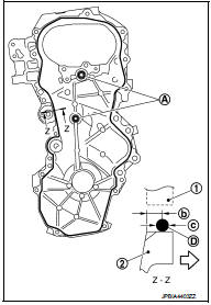
b. Apply a continuous bead of liquid gasket (D) with a tube presser (commercial service tool) to front cover as shown in the figure.
1 : Cylinder head
2 : Front cover
A : Liquid gasket application area
b : 4.0 - 5.6 mm (0.157 - 0.220 in)
c : φ3.4 - 4.4 mm (0.134 - 0.173 in)
 : Engine outside
Use Genuine Liquid Gasket or equivalent.
c. Check that matching marks of timing chain and each sprockets are still aligned. Then install front cover.
CAUTION:
• Check O-ring on cylinder block is correctly installed.
• Be careful not to damage front oil seal by interference with front end of crankshaft.
d. Install front cover, and tighten mounting bolts in numerical order as shown in the figure.
• Refer to the following for the installation position of bolts.
M6 bolt : No. 1
M10 bolts : No. 6, 7, 10, 13, 21
M12 bolts : No. 2, 4, 8, 11
M8 bolts : Except the above
CAUTION:
Attaching should be done within 5 minutes after liquid gasket
application.
e. After all bolts are tightened, retighten them to specified torque in numerical order as shown in the figure.
CAUTION:
Be sure to wipe off any excessive liquid gasket leaking.
12. Install crankshaft pulley with the following procedure: a. When inserting crankshaft pulley with a plastic hammer, tap on its center portion (not circumference).
CAUTION:
Never damage front oil seal lip section.
b. Secure crankshaft pulley (1) with a pulley holder (commercial service tool) (A).
c. Apply new engine oil to thread and seat surfaces of crankshaft pulley bolt.
d. Tighten crankshaft pulley bolt.
 : 29.4 N·m (3.0 kg-m, 22 ft-lb)
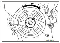
e. Put a paint mark (B) on crankshaft pulley (2), matching with any one of six easy to recognize angle marks (A) on crankshaft pulley bolt (1) flange.
f. Turn another 60 degrees clockwise (angle tightening).
• Check the tightening angle with movement of one angle mark.
g. Check that crankshaft rotates clockwise smoothly.
13. Install remaining parts in the reverse order of removal.
Inspection
INSPECTION AFTER REMOVAL
Timing Chain
Check for cracks (A) and any excessive wear (B) at link plates and
roller links of timing chain. Replace timing chain if necessary.

INSPECTION AFTER INSTALLATION
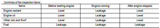
Inspection for Leakage The following are procedures for checking fluids leakage, lubricates leakage, and exhaust gases leakage.
• Before starting engine, check oil/fluid levels including engine coolant and engine oil. If less than required quantity, fill to the specified level. Refer to MA-13, "Fluids and Lubricants".
• Use procedure below to check for fuel leakage.
- Turn ignition switch “ON” (with engine stopped). With fuel pressure applied to fuel piping, check for fuel leakage at connection points.
- Start engine. With engine speed increased, check again for fuel leakage at connection points.
• Run engine to check for unusual noise and vibration.
NOTE
:
If hydraulic pressure inside chain tensioner drops after removal/installation,
slack in guide may generate a
pounding noise during and just after the engine start. However, this does not
indicate an unusualness. Noise
will stop after hydraulic pressure rises.
• Warm up engine thoroughly to check there is no leakage of fuel, or any oil/fluids including engine oil and engine coolant.
• Bleed air from lines and hoses of applicable lines, such as in cooling system.
• After cooling down engine, again check oil/fluid levels including engine oil and engine coolant. Refill to the specified level, if necessary.
*: Transmission/transaxle/CVT fluid, power steering fluid, brake fluid, etc.
 Drive belt auto tensioner and idler pulley
Exploded View
1. Front cover
2. Drive belt auto-tensioner
: N·m (kg-m, ft-lb)
Removal and Installation
Removal
1. Loosen mounting bolt and remove drive belt auto-tensioner.
Installation
I ...
 Camshaft
Exploded View
1. Camshaft position sensor (PHASE)
2. O-ring
3. Camshaft bracket
4. Camshaft (EXH)
5. Camshaft sprocket (EXH)
6. Camshaft sprocket (INT)
7. Camshaft (INT)
8. Valve lifter ...
Other materials:
System
CVT control system : System Diagram
CVT control system : System Description
INPUT/OUTPUT SIGNAL TABLE
*: With Nissan Dynamic Control System
SYSTEM DESCRIPTION
• CVT detects the vehicle driving status from switches, sensors and signals,
and controls the vehicle so that
the optimum shift p ...
Warning lights
All-Wheel Drive (AWD) warning light
(AWD model)
When the ignition switch is in the “ON” position, the All-Wheel Drive (AWD) warning
light will illuminate. It will turn off soon after the engine is started.
If the AWD system malfunctions or the revolution or radius of the front and the
rear ...
Removal and installation
MULTI DISPLAY UNIT
Exploded View
REMOVAL
Refer to IP-12, "Exploded View".
DISASSEMBLY
1. Silencer tape
2. Multi display unit
3. Silencer tape
4. Clip
5. Control finisher
Removal and Installation
REMOVAL
Refer to IP-12, "Exploded View".
CAUTION:
• When perfo ...
