Nissan Juke Service and Repair Manual : System description
COMPONENT PARTS
Circuit Breaker
The PTC thermistor generates heat in response to current flow. The temperature (and resistance) of the thermistor element varies with current flow. Excessive current flow will cause the element's temperature to rise. When the temperature reaches a specified level, the electrical resistance will rise sharply to control the circuit current.
Reduced current flow will cause the element to cool. Resistance falls accordingly and normal circuit current flow is allowed to resume.
Battery
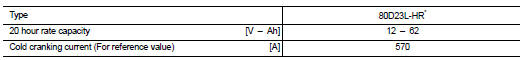
HR*: Because of the frequent battery charge/discharge performed according to a driving condition and a battery condition, this model uses a charge/discharge capacity-enhanced battery. Therefore, it is recommended to use a genuine battery when replacement is needed.
Harness Connector
HARNESS CONNECTOR (TAB-LOCKING TYPE)
• The tab-locking type connectors help prevent accidental looseness or disconnection.
• The tab-locking type connectors are disconnected by pushing or lifting the locking tab(s). Refer to the figure below.
CAUTION:
Never pull the harness or wires when disconnecting the connector.
[Example]
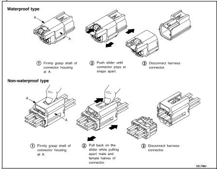
HARNESS CONNECTOR (SLIDE-LOCKING TYPE)
• A new style slide-locking type connector is used on certain systems and components, especially those related to OBD.
• The slide-locking type connectors help prevent incomplete locking and accidental looseness or disconnection.
• The slide-locking type connectors are disconnected by pushing or pulling the slider. Refer to the figure below.
CAUTION:
• Never pull the harness or wires when disconnecting the connector.
• Be careful not to damage the connector support bracket when disconnecting the connector.
[Example]
HARNESS CONNECTOR (LEVER LOCKING TYPE)
• Lever locking type harness connectors are used on certain control units and control modules such as ECM, ABS actuator and electric unit (control unit), etc.
• Lever locking type harness connectors are also used on super multiple junction (SMJ) connectors.
• Always confirm the lever is fully locked in place by moving the lever as far as it will go to ensure full connection.
CAUTION
:
Always confirm the lever is fully released (loosened) before attempting to
disconnect or connect these
connectors to avoid damage to the connector housing or terminals.
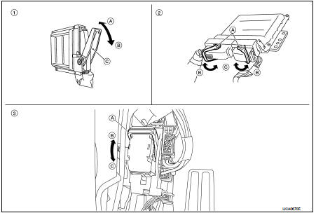
1. Control unit with single lever
A. Fasten
B. Loosen
C. Lever
2. Control unit with dual levers
A. Levers
B. Fasten
C. Loosen
3. SMJ connector
A. Lever
B. Fasten
C. Loosen
Standardized Relay
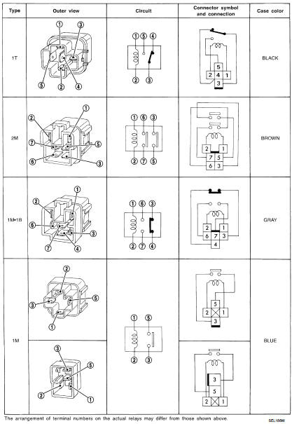
NORMAL OPEN, NORMAL CLOSED AND MIXED TYPE RELAYS
Relays can mainly be divided into three types: normal open, normal closed and mixed type relays.
TYPE OF STANDARDIZED RELAYS
1M ···················· 1 Make 2M ···················· 2 Make
1T ···················· 1 Transfer 1M·1B ···················· 1 Make 1 Break
 Precaution
Precaution for Supplemental Restraint System (SRS) "AIR BAG" and "SEAT
BELT
PRE-TENSIONER"
The Supplemental Restraint System such as “AIR BAG” and “SEAT BELT
PRE-TENSIONER”, ...
 Wiring diagram
...
Other materials:
Fender protector
Exploded View
1. Hoodledge insurator
2. Fender protector
3. U nut
4. Air guide
5. Screw grommet
A. To hoodledge panel
: Vehicle front
Removal and Installation
REMOVAL
1. Remove front fillet molding. Refer to EXT-26, "FRONT FILLET MOLDING :
Removal and Installation".
2. Re ...
Tightening Torque Table (New Standard Included)
CAUTION:
• The special parts are excluded.
• The bolts/nuts in these tables have a strength (discrimination) number/symbol
assigned to the head
or the like. As to the relation between the strength grade in these tables and
the strength (discrimination)
number/symbol, refer to “DISCRIMINATION ...
A/C switch
Component Function Check
1.CHECK A/C ON SIGNAL
With CONSULT-III
1. Turn ignition switch ON.
2. Select “AIR CONDITIONER” of “BCM” using CONSULT-III.
3. Select “AIR COND SW” in “DATA MONITOR” mode, and check status under the
following condition.
Is the inspection result normal?
YES >> ...
