Nissan Juke Service and Repair Manual : System
NISSAN dynamic control system
NISSAN DYNAMIC CONTROL SYSTEM : System Description
SYSTEM DIAGRAM
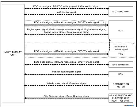
• *1: M/T models except for K9K engine models • *2: CVT models
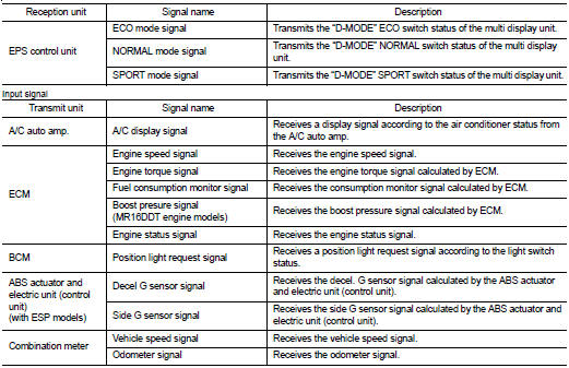
MULTI DISPLAY UNIT INPUT/OUTPUT SINGNAL
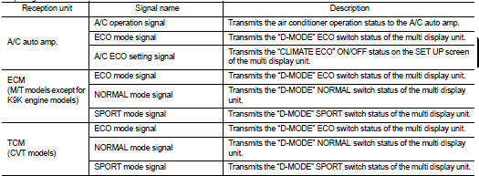
Output signal
SYSTEM DESCRIPTION
• The multi display unit receives necessary information for controlling the following functions from the respective units via CAN communication.
- D-MODE function
- Information display/setting
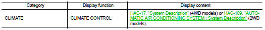
- Air conditioner adjustment function. Refer to HAC-17, "System Description"
(4WD models) or HAC-109,
"AUTOMATIC AIR CONDITIONING SYSTEM : System Description" (2WD models).
• The multi display unit transmits the status of user-selected D-MODE (NORMAL, SPORT, or ECO) to the TCM (CVT models), ECM (M/T models except for K9K engine models), EPS control unit and A/C auto amp.
For the D-MODE functions, refer to DMS-6, "System Description".
• TCM transmits to ECM the D-MODE status (NORMAL, SPORT, or ECO) received from the multi display unit (CVT models).
• ECM (M/T models except for K9K engine models) and EPS control unit receives the D-MODE status (NORMAL, SPORT, or ECO) from the multi display unit.
• The A/C auto amp. receives the air conditioner switch operation signal, ECO mode signal, and ECO mode switch signal from the multi display unit.
• The multi display unit integrates a diagnosis function that allows a diagnosis by CONSULT-III.
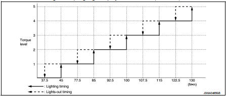
Nissan Dynamic Control System Display/Setting Functions
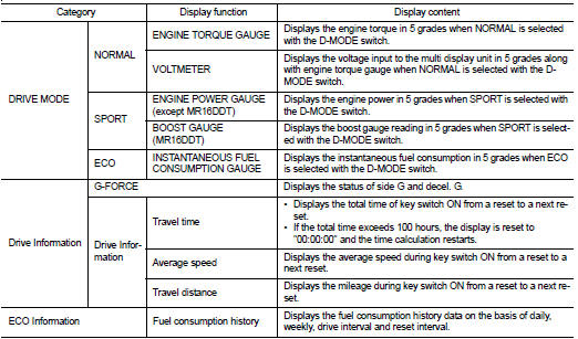
Engine Torque Gauge
The engine torque gauge displays the engine torque level in 5
grades based on the engine torque signal received from ECM via
CAN communication.
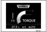
Engine torque gauge display characteristic (HR16DE)
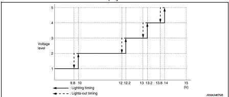
Voltmeter
The voltmeter reads the input voltage of the multi display unit and
displays the voltage level in 5 grades according to the reading.
Voltmeter display characteristic
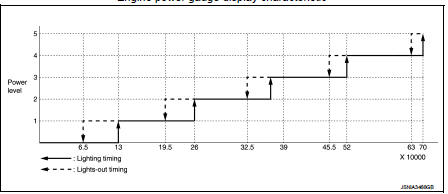
Engine power (except MR16DDT) The engine power gauge displays the engine power level in 5 grades, which is calculated from the engine speed signal and engine torque signal received from ECM via CAN communication.
Engine power gauge display characteristic
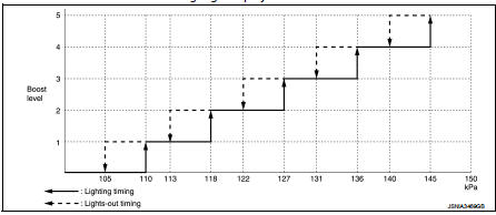
Boost Gauge (MR16DDT) The boost gauge displays the boost level in 5 grades based on the boost pressure signal received from ECM via CAN communication.
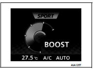
Boost gauge display characteristic
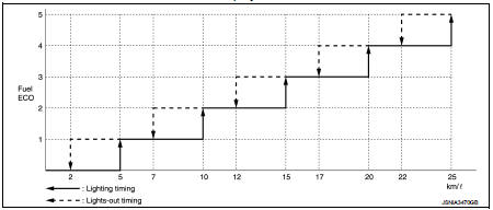
Instantaneous fuel consumption The instantaneous fuel consumption gauge displays the instantaneous fuel consumption in 5 grades, which is calculated from the fuel consumption monitor signal received from ECM via CAN communication and the vehicle speed signal received from the combination meter via CAN communication.
Fuel ECO display characteristic
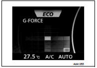
G-Force (With ESP models) The G-FORCE gauge displays the decel G level and side G level in 3 grades respectively, which are calculated based on the decel G sensor signal and side G sensor signal received from the ABS actuator and electric unit (control unit) via CAN communication.
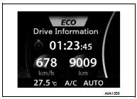
Drive Information
The travel time, average speed, and mileage are displayed as follows.
• Travel time: Displays the time calculated by the multi display unit.
• Average speed: Calculated from the odometer signal and vehicle speed signal received from the combination meter via CAN communication.
• Mileage: Calculated from the odometer signal and vehicle speed signal received from the combination meter via CAN communication.
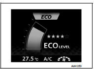
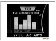
ECO Information
The fuel economy record is calculated from the fuel consumption
monitor signal received from ECM via CAN communication and the
vehicle speed signal received from the combination meter via CAN
communication.
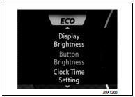
Set Up
The following items can be set.
• Display Brightness
• Button Brightness
• Select Language
• Select Units
• Clock Time Setting
• CLIMATE ECO
• Auto Interior Illumination
• Selective Door Unlock
• Auto Headlight Sensitivity
Display/operation restrictions • To secure safety, some functions are not allowed for user operation during driving.
• The functions subject to the display/operation restriction are as follows.
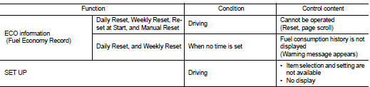
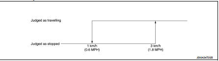
Driving status judgment criterion • The driving status is judged from the vehicle speed signal received from the combination meter via CAN communication. The driving status is displayed on the multi display unit and operation restrictions are applied as necessary.
 Component parts
Component Parts Location
1. A/C auto amp.
Refer to HAC-12, "Component Parts
Location".
2. ABS actuator and electric unit (control
unit)
Refer to BRC-9, "Component Parts
Locatio ...
 Handling precaution
Nissan Dynamic Control System
• The engine torque, engine power, boost, and instantaneous fuel consumption
are provided for information
purposes only. They are not intended to prompt the driver to ...
Other materials:
Doors
WARNING
• Always have the doors locked while driving. Along with the use of
seat belts, this provides greater safety in the event of an accident by helping
to prevent persons from being thrown from the vehicle. This also helps keep children
and others from unintentionally opening the do ...
Encoder circuit
Component Function Check
1.CHECK ENCODER OPERATION
Check that front driver side door glass perform AUTO UP/DOWN operation
normally when power window
main switch is operated.
Is the inspection result normal?
YES >> INSPECTION END
NO >> Refer to PWC-30, "Diagnosis Procedure& ...
Front wheel hub and K
Exploded View
1. Steering knuckle
2. Splash guard
3. Hub bolt
4. Wheel hub assembly (Bearing-integrated
type)
5. Disc rotor
6. Wheel hub lock nut
7. Adjusting cap
8. Cotter pin
A. Tightening must be done following the installation procedure. Refer to
FAX-68, "Removal and Insta ...
