Nissan Juke Service and Repair Manual : System
Headlamp system
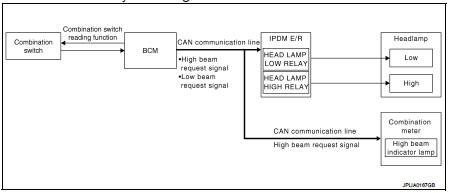
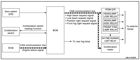
HEADLAMP SYSTEM : System Diagram
HEADLAMP SYSTEM : System Description
OUTLINE
Headlamp is controlled by combination switch reading function and headlamp control function of BCM, and relay control function of IPDM E/R.
HEADLAMP (LO) OPERATION
• BCM detects the combination switch condition with the combination switch reading function.
• BCM transmits the low beam request signal to IPDM E/R using CAN communication according to the headlamp (LO) ON condition.
Headlamp (LO) ON condition
- Lighting switch 2ND
- Lighting switch AUTO (auto light function ON judgment)
- Lighting switch AUTO, with the front fog lamp switch ON and the ignition
switch ON
• IPDM E/R turns the integrated headlamp low relay ON, and turns the headlamp ON according to the low beam request signal.
HEADLAMP (HI) OPERATION
• BCM transmits the high beam request signal to IPDM E/R and the combination meter using CAN communication according to the headlamp (HI) ON condition. At this time, BCM stops to transmit low beam request signal.
Headlamp (HI) ON condition
- Lighting switch HI with the lighting switch 2ND or AUTO (auto light function
ON judgment)
- Lighting switch PASS
- Lighting switch AUTO, with the front fog lamp switch ON, the ignition switch
ON and lighting switch HI.
• Combination meter turns the high beam indicator lamp ON according to the high beam request signal.
• IPDM E/R turns the integrated headlamp high relay ON, and turns the headlamp ON according to the high beam request signal.
FOLLOW ME HOME FUNCTION
When the driver is moving to the house entrance from the own vehicle, headlamp is kept still ON by the follow me home function of BCM.
• When BCM detects the input of lighting switch PASS while all of following conditions satisfied, it transmits the low beam request signal for a period of time to IPDM E/R through CAN communication.
Follow me home ON condition
- Ignition switch OFF
- Lighting switch OFF
• IPDM E/R turns the integrated headlamp low relay ON, and turns the headlamp ON according to the low beam request signal.
• When in any of following conditions, follow me home function can be cancelled while follow me home function is operating.
Follow me home OFF condition - Ignition switch is turned from OFF→ACC or ON - Lighting switch is turned from OFF→ON
NOTE
:
• Flash-to-pass operation illumination time for 1 time can be extended to
approximately 30 seconds during
operation of follow me home function.
• Flash-to-pass operation can be illuminated continuously for approximately 60 seconds (flash-to-pass operation, 2 times), approximately 90 seconds (flash-to-pass operation, 3 times), and a maximum of approximately 120 seconds (flash-to-pass operation, 4 times).
• Follow me home function activating time can be set by CONSULT-III. Refer to EXL-20, "HEADLAMP : CONSULT- III Function (BCM - HEAD LAMP)"(with Intelligent Key), EXL-25, "HEADLAMP : CONSULT-III Function (BCM - HEAD LAMP)"(without Intelligent Key).
HEADLAMP SYSTEM : Fail-Safe
CAN COMMUNICATION CONTROL
When CAN communication with ECM and BCM is impossible, IPDM E/R performs fail-safe control. After CAN communication recovers normally, it also returns to normal control.
If No CAN Communication Is Available With BCM

Auto light system (without DTRL)
AUTO LIGHT SYSTEM (WITHOUT DTRL) : System Di
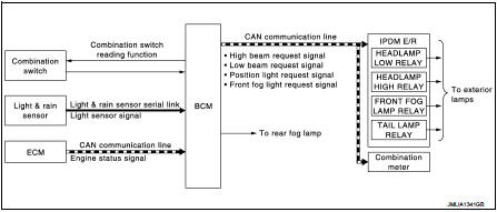
AUTO LIGHT SYSTEM (WITHOUT DTRL) : System Description
OUTLINE
• Auto light system is controlled by each function of BCM and IPDM E/R.
Control by BCM
- Combination switch reading function
- Headlamp control function
- Auto light function
Control by IPDM E/R
- Relay control function
• Auto light function turns the exterior lamps* ON/OFF automatically according
to the outside brightness.
*: Headlamp (LO/HI), parking, license plate and tail lamps (Headlamp HI depends on the combination switch condition.) license plate lamp
AUTO LIGHT FUNCTION
• BCM detects the combination switch condition with the combination switch reading function.
• BCM detects the engine condition by the engine status signal received from ECM via CAN communication.
• BCM receives exterior lamp ON/OFF requests from the light & rain sensor by light & rain sensor serial link.
• BCM judges the ON/OFF status of the exterior lamp according to ON/OFF requests from light & rain sensor and the vehicle condition.
• BCM transmits each request signal to IPDM E/R via CAN communication according to ON/OFF condition by the auto light function.
NOTE
:
ON/OFF timing differs based on the sensitivity from the setting. The setting can
be set by CONSULT-III. Refer
to EXL-20, "HEADLAMP : CONSULT-III Function (BCM - HEAD LAMP)".
Auto light system (with DTRL)
AUTO LIGHT SYSTEM (WITH DTRL) : System Diagram
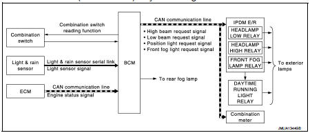
AUTO LIGHT SYSTEM (WITH DTRL) : System Description
OUTLINE
• Auto light system is controlled by each function of BCM and IPDM E/R.
Control by BCM
- Combination switch reading function
- Headlamp control function
- Auto light function
Control by IPDM E/R
- Relay control function
• Auto light function turns the exterior lamps* ON/OFF automatically according
to the outside brightness.
*: Headlamp (LO/HI), parking lamp, tail lamp (Headlamp HI depends on the combination switch condition.) AUTO LIGHT FUNCTION
• BCM detects the combination switch condition with the combination switch reading function.
• BCM detects the engine condition by the engine status signal received from ECM via CAN communication.
• BCM receives exterior lamp ON/OFF requests from the light & rain sensor by light & rain sensor serial link.
• BCM judges the ON/OFF status of the exterior lamp according to ON/OFF requests from light & rain sensor and the vehicle condition.
• BCM transmits each request signal to IPDM E/R via CAN communication according to ON/OFF condition by the auto light function.
NOTE
:
ON/OFF timing differs based on the sensitivity from the setting. The setting can
be set by CONSULT-III. Refer
to EXL-20, "HEADLAMP : CONSULT-III Function (BCM - HEAD LAMP)".
Daytime running light system
DAYTIME RUNNING LIGHT SYSTEM : System Diagram
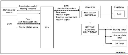
DAYTIME RUNNING LIGHT SYSTEM : System Description
OUTLINE
• Turns the following exterior lamps ON as the daytime running light.
- Headlamp (LO)
- Parking, license plate and tail lamps.
• Daytime running light is controlled by daytime running light control function and combination switch reading function of BCM, and relay control function of IPDM E/R.
DAYTIME RUNNING LIGHT OPERATION
• BCM detects the combination switch condition by the combination switch reading function.
• BCM detects vehicle condition depending on the following signals.
- Engine status signal (received from ECM via CAN communication) • BCM transmits the low beam request signal and daytime running light request signal to IPDM E/R via CAN communication according to the daytime running light ON condition.
Daytime running light ON condition
- Engine running
- Lighting switch OFF
- Auto light switch is ON, front fog lamp switch and rear fog lamp switch are
OFF, and auto light judgement is
OFF.
• IPDM E/R turns the integrated headlamp low relay and daytime running light relay ON according to the low beam request signal and daytime running light request signal. And it turns each lamps ON.
Headlamp aiming control (manual)
HEADLAMP AIMING CONTROL (MANUAL) : System Description
The headlamp levelizer adjusts the headlamp light axis upward and downward with the aiming motor integrated in the front combination lamp.
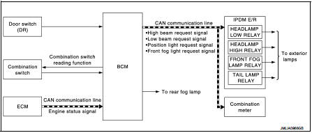
Front fog lamp system
FRONT FOG LAMP SYSTEM : System Diagram
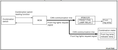
FRONT FOG LAMP SYSTEM : System Description
OUTLINE
Front fog lamp is controlled by combination switch reading function and front fog lamp control function of BCM, and relay control function of IPDM E/R.
FRONT FOG LAMP OPERATION
• BCM detects the combination switch condition by the combination switch reading function.
• BCM transmits the front fog lights request signal to IPDM E/R and the combination meter via CAN communication according to the front fog lamp ON condition.
Front fog lamp ON condition - Front fog lamp switch ON and any of the followings.
• Lighting switch 1ST
• Lighting switch 2ND
• Lighting switch AUTO and the ignition switch ON
IPDM E/R turns the integrated front fog lamp relay ON, and turns the front fog lamp ON according to the front fog lights request signal.
Combination meter turns the front fog lamp indicator lamp ON according to the front fog lights request signal.
FRONT FOG LAMP SYSTEM : Fail-Safe
CAN COMMUNICATION CONTROL When CAN communication with ECM and BCM is impossible, IPDM E/R performs fail-safe control. After CAN communication recovers normally, it also returns to normal control.
If No CAN Communication Is Available With BCM

Rear fog lamp system
REAR FOG LAMP SYSTEM : System Diagram
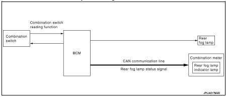
REAR FOG LAMP SYSTEM : System Description
OUTLINE
Rear fog lamp is controlled with the combination switch reading function and the rear fog lamp control function of BCM.
REAR FOG LAMP OPERATION
• BCM detects the condition of the combination switch by the combination switch reading function.
• BCM supplies voltage to rear fog lamp according to the rear fog lamp ON condition.
Rear fog lamp switch is turned from OFF to ON with any of following condition.
- Lighting switch 2ND
- Lighting switch AUTO and the ignition switch ON
- Front fog lamp ON
• BCM transmits the rear fog lamp status signal to the combination meter using CAN communication.
• Combination meter turns the rear fog lamp indicator lamp ON according to the rear fog lamp status signal.
Turn signal and hazard warning lamp system
TURN SIGNAL AND HAZARD WARNING LAMP SYSTEM : System Diagram
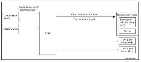
TURN SIGNAL AND HAZARD WARNING LAMP SYSTEM : System Description
OUTLINE
Turn signal lamp and the hazard warning lamp is controlled by combination switch reading function and the flasher control function of BCM.
TURN SIGNAL LAMP OPERATION
• BCM detects the combination switch condition by the combination switch reading function.
• BCM supplies voltage to the right (left) turn signal lamp circuit when the ignition switch is ON and the turn signal switch is in the right (left) position. BCM blinks the turn signal lamp.
HAZARD WARNING LAMP OPERATION
BCM supplies voltage to both turn signal lamp circuit when the hazard switch is ON. BCM blinks the hazard warning lamp.
TURN SIGNAL INDICATOR LAMP AND TURN SIGNAL OPERATION
• BCM transmits the turn signal indicator lamp signal to the combination meter using CAN communication while the turn signal lamp and the hazard warning lamp are operating.
• Combination meter outputs the turn signal sound with the integrated buzzer while blinking the turn signal indicator lamp according to the turn signal indicator lamp signal.
3-TIME FLASHER FUNCTION
• By a short touch of the turn signal lever, BCM blinks the turn signal lamps 3 times in the selected direction.
• Cancel the operation when short touch of the turn signal lever in the reverse direction during the 3-time flasher function operating.
HIGH FLASHER OPERATION
• BCM detects the turn signal lamp circuit status from the current value.
• BCM increases the turn signal lamp blinking speed if the bulb or harness open is detected with the turn signal lamp operating.
NOTE
:
The blinking speed is normal while operating the hazard warning lamp.
Parking, license plate and tail lamp system (without DTRL)
PARKING, LICENSE PLATE AND TAIL LAMP SYSTEM (WITHOUT DTRL) : System Diagram
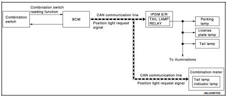
PARKING, LICENSE PLATE AND TAIL LAMP SYSTEM (WITHOUT DTRL) : System Description
OUTLINE
Parking, license plate and tail lamps are controlled by combination switch reading function and headlamp control function of BCM, and relay control function of IPDM E/R.
PARKING, LICENSE PLATE AND TAIL LAMPS OPERATION
• BCM detects the combination switch condition by the combination switch reading function.
• BCM transmits the position light request signal to IPDM E/R and the combination meter via CAN communication according to the ON/OFF condition of the parking, license plate and tail lamps.
Parking, license plate and tail lamps ON condition
- Lighting switch 1ST
- Lighting switch 2ND
- Lighting switch AUTO, and the auto light function ON judgment
- Lighting switch AUTO, with the front fog lamp switch ON and the ignition
switch ON
• IPDM E/R turns the integrated tail lamp relay ON and turns the parking, license plate and tail lamps ON according to the position light request signal.
• Combination meter turns the tail lamp indicator lamp ON according to the position light request signal.
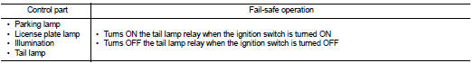
PARKING, LICENSE PLATE AND TAIL LAMP SYSTEM (WITHOUT DTRL) : Fail-Safe
CAN COMMUNICATION CONTROL
When CAN communication with ECM and BCM is impossible, IPDM E/R performs fail-safe control. After CAN communication recovers normally, it also returns to normal control.
If No CAN Communication Is Available With BCM
Parking, license plate and tail lamp system (with DTRL)
PARKING, LICENSE PLATE AND TAIL LAMP SYSTEM (WITH DTRL) : System Diagram
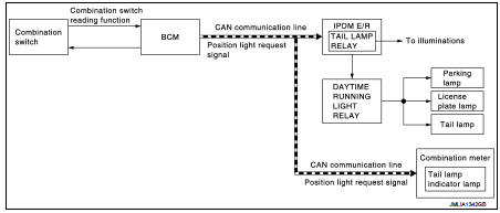
PARKING, LICENSE PLATE AND TAIL LAMP SYSTEM (WITH DTRL) : System Description
OUTLINE
Parking, license plate and tail lamps are controlled by combination switch reading function and headlamp control function of BCM, and relay control function of IPDM E/R.
PARKING, LICENSE PLATE AND TAIL LAMPS OPERATION
• BCM detects the combination switch condition by the combination switch reading function.
• BCM transmits the position light request signal to IPDM E/R and the combination meter via CAN communication according to the ON/OFF condition of the parking, license plate and tail lamps.
Parking, license plate and tail lamps ON condition
- Lighting switch 1ST
- Lighting switch 2ND
- Lighting switch AUTO, and the auto light function ON judgment
- Lighting switch AUTO, with the front fog lamp switch ON and the ignition
switch ON
• IPDM E/R turns the daytime running light relay ON and turns the parking,
license plate and tail lamps ON
according to the position light request signal.
• Combination meter turns the tail lamp indicator lamp ON according to the position light request signal.
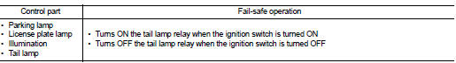
PARKING, LICENSE PLATE AND TAIL LAMP SYSTEM (WITH DTRL) : Fail-Safe
CAN COMMUNICATION CONTROL
When CAN communication with ECM and BCM is impossible, IPDM E/R performs fail-safe control. After CAN communication recovers normally, it also returns to normal control.
If No CAN Communication Is Available With BCM
Exterior lamp battery saver system (without DTRL)
EXTERIOR LAMP BATTERY SAVER SYSTEM (WITHOUT DTRL) : System Diagram
EXTERIOR LAMP BATTERY SAVER SYSTEM (WITHOUT DTRL) : System Description
OUTLINE
• Exterior lamp battery saver system is controlled by each function of BCM and IPDM E/R.
Control by BCM
- Combination switch reading function
- Headlamp control function
- Exterior lamp battery saver function
Control by IPDM E/R
- Relay control function
• BCM turns the exterior lamps* OFF after a period of time to prevent the battery from over-discharge when the ignition switch is turned OFF with the exterior lamps ON.
*: Headlamp (LO/HI), parking lamp, tail lamp, license plate lamp, front fog lamp and rear fog lamp EXTERIOR LAMP BATTERY SAVER ACTIVATION
BCM turns the exterior lamps OFF (battery saver is activated) when all of following condition.
• Exterior lamps ON
• When any of the following conditions is satisfied.
- Driver side door switch is turned from OFF to ON while ignition switch is OFF.
- Ignition switch is turned from ON to OFF while driver side door switch is ON.
NOTE
:
When following condition (after the exterior lamp battery saver is activated),
exterior lamps can be turned ON.
• Lighting switch ON→ OFF → ON
Exterior lamp battery saver system (with DTRL)
EXTERIOR LAMP BATTERY SAVER SYSTEM (WITH DTRL) : System Diagram
EXTERIOR LAMP BATTERY SAVER SYSTEM (WITH DTRL) : System Description
OUTLINE
• Exterior lamp battery saver system is controlled by each function of BCM and IPDM E/R.
Control by BCM
- Combination switch reading function
- Headlamp control function
- Exterior lamp battery saver function
Control by IPDM E/R
- Relay control function
• BCM turns the exterior lamps* OFF after a period of time to prevent the battery from over-discharge when the ignition switch is turned OFF with the exterior lamps ON.
*: Headlamp (LO/HI), parking lamp, tail lamp, license plate lamp, front fog lamp and rear fog lamp EXTERIOR LAMP BATTERY SAVER ACTIVATION
BCM turns the exterior lamps OFF (battery saver is activated) when all of following condition.
• Exterior lamps ON
• When any of the following conditions is satisfied.
- Driver side door switch is turned from OFF to ON while ignition switch is OFF.
- Ignition switch is turned from ON to OFF while driver side door switch is ON.
NOTE
:
When following condition (after the exterior lamp battery saver is activated),
exterior lamps can be turned ON.
• Engine running
• Lighting switchON→ OFF → ON
 Component parts
Component Parts Location
1. Hazard switch
2. Parking lamp
3. Front turn signal lamp
4. Front fog lamp*1
5. Headlamp
6. ECM
Refer to EC-461, "ECM".
7. IPDM E/R
Refer to PCS-5, ...
 Diagnosis system (BCM) (with intelligent key system)
Common item
COMMON ITEM : CONSULT-III Function (BCM - COMMON ITEM)
APPLICATION ITEM
CONSULT-III performs the following functions via CAN communication with BCM.
SYSTEM APPLICATION
BCM can perfo ...
Other materials:
Diagnosis and repair work flow
Flowchart of Trouble Diagnosis
NOTE:
“DTC” includes DTC at the 1st trip.
1.OBTAIN INFORMATION ABOUT SYMPTOM
1. Refer to TM-372, "Question sheet" and interview the customer to obtain the
malfunction information (conditions
and environment when the malfunction occurred) as much as p ...
Service Notice
• When removing or installing various parts, place a cloth or padding onto
the vehicle body to prevent
scratches.
• Handle trim, molding, instruments, grille, etc. carefully during removing or
installing. Be careful not to oil or
damage them.
• Apply sealing compound where necessary when ins ...
Component parts
Component Parts Location
LHD models
1. Multi display unit*
Refer to DMS-3, "Component Parts
Location".
2. ABS actuator and electric unit (control
unit)
Refer to BRC-9, "Component Parts
Location" (without ESP), BRC-97,
"Component Parts Location" (with
ESP).
...
