Nissan Juke Service and Repair Manual : System
Intelligent key system/engine start function
INTELLIGENT KEY SYSTEM/ENGINE START FUNCTION : System Diagram

INTELLIGENT KEY SYSTEM/ENGINE START FUNCTION : System
SYSTEM DESCRIPTION
• The engine start function of Intelligent Key system makes it possible to start and stop the engine without using the key, based on the electronic ID verification. The electronic ID verification is performed between BCM and Intelligent Key when the push-button ignition switch is pressed while the Intelligent Key is within the detection area of inside key antenna.
NOTE
:
The driver should carry the Intelligent Key at all times.
• Intelligent Key has 2 IDs [Intelligent Key ID and NVIS (NATS) ID]. It can perform the door lock/unlock operation and the push-button ignition switch operation when the registered Intelligent Key is carried.
• When Intelligent Key battery is discharged, engine can be started by operating push-button ignition switch after contacting Intelligent Key backside to push-button ignition switch. At that time, the NVIS (NATS) ID verification is performed.
• If the ID is successfully verified, when push-button ignition switch is pressed, steering lock is released and the engine can be started.
• Up to 4 Intelligent Keys can be registered (Including the standard Intelligent Key) upon request from the customer.
NOTE
:
Refer to DLK-27, "INTELLIGENT KEY SYSTEM : System Description" (With super lock)
or DLK-204,
"INTELLIGENT KEY SYSTEM : System Description" (Without super lock) for any
functions other than
engine start function of Intelligent Key system.
PRECAUTIONS FOR INTELLIGENT KEY SYSTEM
The transponder [the chip for NVIS (NATS) ID verification] is integrated into the Intelligent Key. (For the conventional models, it is integrated into the mechanical key.) Therefore, ID verification cannot be performed by mechanical key only.
In that case, the NVIS (NATS) ID verification can be performed when Intelligent Key backside is contacted to push-button ignition switch. If verification result is OK, engine can be started.
OPERATION WHEN INTELLIGENT KEY IS CARRIED
1. When the push-button ignition switch is pressed, the BCM activates the inside key antenna and transmits the request signal to the Intelligent Key.
2. The Intelligent Key receives the request signal and transmits the Intelligent Key ID signal to the BCM.
3. BCM receives the Intelligent Key ID signal via remote keyless entry receiver and verifies it with the registered ID.
4. BCM transmits the unlock signal to steering lock unit and IPDM E/R if the verification results are OK.
5. IPDM E/R turns the steering lock relay ON and supplies power supply to the steering lock unit.
6. The steering lock releases.
7. BCM transmits the power supply stop signal to IPDM E/R when detecting that the steering lock is in the unlock condition.
8. IPDM E/R turns the steering lock relay OFF and stops power supply to the steering lock unit.
9. BCM turns ACC relay ON and transmits the ignition power supply ON signal to IPDM E/R.
10. IPDM E/R turns the ignition relay ON and starts the ignition power supply.
11. BCM detects that the selector lever position and brake pedal operating condition (CVT models), or shift lever position and clutch pedal operation condition (M/T models).
12. BCM transmits the starter request signal to IPDM E/R and turns the starter relay in IPDM E/R ON if BCM judges that the engine start condition* is satisfied.
13. IPDM E/R turns the starter control relay ON when receiving the starter request signal.
14. Power supply is supplied through the starter relay and the starter control relay to operate the starter motor.
CAUTION:
If a malfunction is detected in the Intelligent Key system, the “KEY” warning
lamp in the combination
meter illuminates. At that time, the engine cannot be started
.
15. When BCM receives feedback signal from ECM indicating that the engine is
started, the BCM transmits a
stop signal to IPDM E/R and stops cranking by turning OFF the starter motor
relay. (If engine start is
unsuccessful, cranking stops automatically within 5 seconds.)
CAUTION:
When the Intelligent Key is carried outside of the vehicle (inside key antenna
detection area) while
the power supply is in the ACC or ON position, even if the engine start
condition* is satisfied, the
engine cannot be started.
*: For the engine start condition, refer to “POWER SUPPLY POSITION CHANGE TABLE BY PUSH-BUTTON IGNITION SWITCH OPERATION”.
OPERATION RANGE
Engine can be started when Intelligent Key is inside the vehicle. However, sometimes engine may not start when Intelligent Key is on instrument panel or in glove box.
ENGINE START OPERATION WHEN INTELLIGENT KEY IS CONTACTED TO PUSH-BUTTON IGNITION SWITCH
When Intelligent Key battery is discharged, the NVIS (NATS) ID verification between transponder in Intelligent Key and BCM is performed when Intelligent Key backside is contacted to push-button ignition switch. If the verification result is OK, engine can be started.
STEERING LOCK OPERATION
Steering is locked by steering lock unit when any of the following conditions are met.
• When ignition switch is in the OFF position, selector lever is in the P position, and any of the following conditions are met.
- Closing door
- Opening door
- Door is locked using door request switch
- Door is locked using Intelligent Key
• When BCM power consumption control system is released by meeting any of the following conditions.
- Opening any door
- Operating door lock using door request switch
- Operating door lock using Intelligent Key
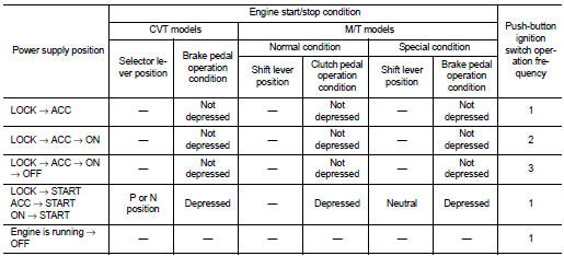
POWER SUPPLY POSITION CHANGE TABLE BY PUSH-BUTTON IGNITION SWITCH OPERATION
The power supply position changing operation can be performed with the following operations.
NOTE
:
• When an Intelligent Key is within the detection area of inside key antenna and
when Intelligent Key backside
is contacted to push-button ignition switch, it is equivalent to the operations
below.
• When starting the engine, the BCM monitors under the engine start conditions,
CVT models
- Brake pedal operating condition
- Selector lever position
- Vehicle speed
M/T models
- Clutch pedal operating condition
- Brake pedal operating condition
- Shift lever position
- Vehicle speed
Vehicle speed: less than 4 km/h (2.5 MPH)
Vehicle speed: 4 km/h (2.5 MPH) or more
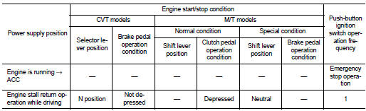
Emergency stop operation
• Press and hold the push-button ignition switch for 2 seconds or more.
• Press the push-button ignition switch 3 times or more within 1.5 seconds.
NISSAN vehicle immobilizer system-nats
NISSAN VEHICLE IMMOBILIZER SYSTEM-NATS : System Diagram

NISSAN VEHICLE IMMOBILIZER SYSTEM-NATS : System Description
SYSTEM DESCRIPTION
• The NISSAN VEHICLE IMMOBILIZER SYSTEM-NATS [NVIS (NATS)] prevents the engine from being started by Intelligent Key whose ID is not registered to the vehicle (BCM). It has higher protection against auto theft involving the duplication of mechanical keys.
• The ignition key integrated in the Intelligent Key cannot start the engine. When the Intelligent Key battery is discharged, the NVIS (NATS) ID verification is performed between the transponder integrated with Intelligent Key and BCM via NATS antenna amp. when the Intelligent Key backside is contacted to push-button ignition switch. If the verification results are OK, the engine start operation can be performed by the push-button ignition switch operation.
• The security indicator lamp on combination meter always blinks when the power supply position is any position other than ON which warns that the NVIS (NATS) is on board the model.
• Up to 4 Intelligent Keys can be registered (including the standard ignition key) upon request from the owner.
• Specified registration is required when replacing ECM, BCM or Intelligent Key. For the registration procedures, refer to CONSULT-III Operation Manual IVIS-NVIS/NATS.
• Possible symptom of NVIS (NATS) malfunction is “Engine cannot start”. The engine can not be started because of other than NVIS (NATS) malfunction, so start the trouble diagnosis according to SEC-47, "Work Flow".
• If ECM other than genuine part is installed, the engine cannot be started. For ECM replacement procedure, refer to EC-133, "Work Procedure" (MR16DDT), EC-541, "Work Procedure" (HR16DE) or EC-879, "Work Procedure" (K9K).
PRECAUTIONS FOR KEY REGISTRATION
• The ID registration is a procedure that erases the current NVIS (NATS) ID once, and then reregisters a new ID. Therefore before starting the registration operation, collect all registered Intelligent Keys from the customer.
• When registering the Intelligent Key, perform only one procedure to simultaneously register both ID [NVIS (NATS) ID and Intelligent Key ID].
SECURITY INDICATOR LAMP
• Warns that the vehicle is equipped with NVIS (NATS).
• Security indicator lamp always blinks when the power supply position is any position other than ON.
NOTE
:
Because security indicator lamp is highly efficient, the battery is barely
affected.
ENGINE START OPERATION WHEN INTELLIGENT KEY IS CONTACTED TO PUSH-BUTTON IGNITION SWITCH
1. When brake pedal is depressed while selector lever is in the P position, BCM activates NATS antenna amp. that is located behind push-button ignition switch.
2. When Intelligent Key (transponder built-in) backside is contacted to push-button ignition switch, BCM starts NVIS (NATS) ID verification between BCM and Intelligent Key (transponder built-in) via NATS antenna amp.
3. When the NVIS (NATS) ID verification result is OK, buzzer in combination meter sounds and BCM transmits the result to ECM.
4. When push-button ignition switch is pressed, BCM transmits steering unlock signal to steering lock unit and IPDM E/R.
5. IPDM E/R turns steering lock relay ON and supplies power supply to the steering lock unit.
6. The steering lock is released.
7. BCM transmits the power supply stop signal to IPDM E/R when detecting that the steering lock is in the unlock position.
8. IPDM E/R turns steering lock relay OFF and stops power supply to the steering lock unit.
9. BCM turns ACC relay ON and transmits ignition power supply ON signal to IPDM E/R.
10. IPDM E/R turns the ignition relay ON and starts the ignition power supply.
11. BCM detects that the selector lever position and brake pedal operating condition (CVT models), or shift lever position and clutch pedal operation condition (M/T models).
12. BCM transmits starter request signal to IPDM E/R and turns the starter relay in IPDM E/R ON if BCM judges that the engine start condition* is satisfied.
13. IPDM E/R turns the starter control relay ON when receiving the starter request signal.
14. Power supply is supplied through the starter relay and the starter control relay to operate the starter motor.
15. When BCM receives feedback signal from ECM indicating that the engine is started, BCM transmits a stop signal to IPDM E/R and stops cranking by turning off the starter motor relay. (If engine start is unsuccessful, cranking stops automatically within 5 seconds.) *: For the engine start condition, refer to “POWER SUPPLY POSITION CHANGE TABLE BY PUSH-BUTTON IGNITION SWITCH OPERATION” below.
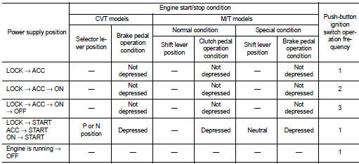
POWER SUPPLY POSITION CHANGE TABLE BY PUSH-BUTTON IGNITION SWITCH OPERATION
The power supply position changing operation can be performed with the following operations.
NOTE
:
• When an Intelligent Key is within the detection area of inside key antenna and
when Intelligent Key backside
is contacted to push-button ignition switch, it is equivalent to the operations
below.
• When starting the engine, the BCM monitors under the engine start conditions,
CVT models
- Brake pedal operating condition
- Selector lever position
- Vehicle speed
M/T models
- Clutch pedal operating condition
- Brake pedal operating condition
- Shift lever position
- Vehicle speed
Vehicle speed: less than 4 km/h (2.5 MPH)
Vehicle speed: 4 km/h (2.5 MPH) or more
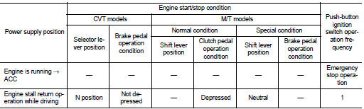
Emergency stop operation • Press and hold the push-button ignition switch for 2 seconds or more.
• Press the push-button ignition switch 3 times or more within 1.5 seconds.
Vehicle security system
VEHICLE SECURITY SYSTEM : System Diagram
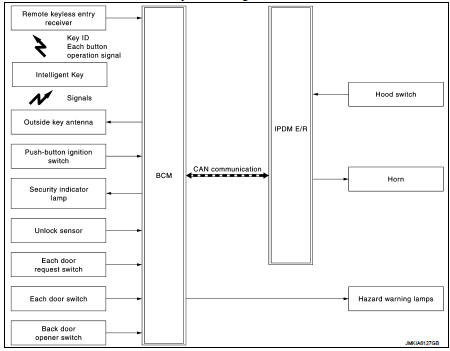
VEHICLE SECURITY SYSTEM : System Description
• The vehicle security system has two alarm functions (theft warning alarm and panic alarm), and reduces the possibility of a theft or mischief by activating horns and hazard warning lamps intermittently.
• The panic alarm does not start when the theft warning alarm is activating, and the panic alarm stops when the theft warning alarm is activated.
The priority of the functions are as per the following.

THEFT WARNING ALARM
• The theft warning alarm function activates horns and hazard warning lamps intermittently when BCM detects that any door or hood is opened by unauthorized means, while the system is in the ARMED state.
• Security indicator lamp on combination meter always blinks when power supply position is any position other than ON. Security indicator lamp blinking warns that the vehicle is equipped with a vehicle security system.
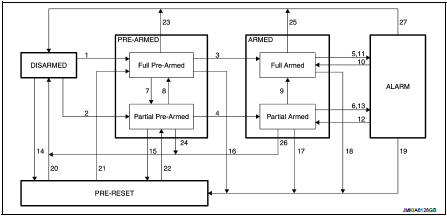
Operation Flow
NOTE
:
• To lock/unlock all doors by operating remote controller button of Intelligent
Key or door request switch, Intelligent Key must be within
the detection area of outside key antenna. For details, refer to DLK-28, "DOOR
LOCK FUNCTION : System Description" (Models with
super lock) or DLK-205, "DOOR LOCK FUNCTION : System Description" (Models
without super lock).
• To open back door by operating back door opener switch, Intelligent Key must be within the detection area of outside key antenna. For details, refer to DLK-32, "BACK DOOR OPEN FUNCTION : System Description" (Models with super lock) or DLK-208, "BACK DOOR OPEN FUNCTION : System Description" (Models without super lock).
DISARMED Phase
The vehicle security system is not set in the DISARMED phase. Security indicator
lamp blinks every 2.4 seconds.
When the vehicle security system is reset, each phase switches to the DISARMED phase directly.
PRE-ARMED Phase
The PRE-ARMED phase is the transient state between the DISARMED phase and the
ARMED phase. This
phase is maintained for 20 seconds, so that the owner can reset the setting due
to a mis-operation. This phase
switches to the ARMED phase when vehicle conditions are not changed for 20
seconds.
There are two type of phase (Full Pre-Armed and Partial Pre-Armed).
• Full Pre-Armed phase
Vehicle security system enters into this phase when all doors are closed.
Security indicator lamp blinks at 8
Hz while being in this phase. If any door is opened during this phase, the
system status changes to Partial
Pre-Armed phase.
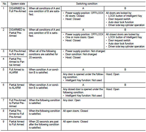
To reset this phase, refer to the switching condition of No. 23 in the table above.
• Partial Pre-Armed phase Vehicle security system enters into this phase when one or more doors are open. Security indicator lamp blinks at 2.5 Hz while being in this phase. If all doors are closed during this phase, the system status changes to Full Pre-Armed phase.
To reset this phase, refer to the switching condition of No. 24 in the table above.
ARMED Phase
The vehicle security system is set, and BCM monitors all necessary inputs. If
any door or hood is opened by
unauthorized means, vehicle security system switches to the ALARM phase.
Security indicator lamp blinks
every 2.4 seconds.
There are two type of phase (Full Armed and Partial Armed).
• Full Armed phase
Vehicle security system enters into this phase from Full Pre-Armed phase.
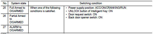
To reset this phase, refer to the switching condition of No. 25 in the table above.
• Partial Armed phase
Vehicle security system enters into this phase from Partial Pre-Armed phase. If
all doors are closed during
this phase, the system status changes to Full Armed phase.
To reset this phase, refer to the switching condition of No. 26 in the table above.
ALARM Phase
BCM transmits “Theft Warning Horn Request” signal intermittently to IPDM E/R via
CAN communication and
blinks hazard warning lamps. In this phase, horns and hazard warning lamps are
activated intermittently for
approximately 27.5 seconds to warn that the vehicle is accessed by unauthorized
means.
Horns are sounding at 2.5 Hz, and hazard warning lamps blinks at 1.42 Hz.
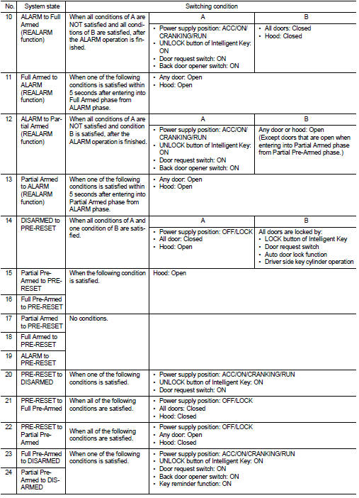
To cancel the ALARM operation, refer to the switching condition of No. 27 in the table above.
NOTE
:
If a battery terminal is disconnected during the ALARM phase, theft warning
alarm stops. But when the battery
terminal is reconnected, theft warning alarm is activated again.
REALARM Phase
When ALARM phase is maintained for 27.5 seconds without any cancel operation, the system status returns to the ARMED phase. At this time, if BCM still detects unauthorized access to the vehicle, the system is switched to the ALARM phase again. This REALARM operation is carried out a maximum of 8 times.
PRE-RESET Phase
The PRE-RESET phase is the transient state between each phase and DISARMED
phase. If only the condition
of hood is not satisfied, the system switches to the PRE-RESET phase. Then, when
any condition is
changed, the system switches to the DISARMED phase or PRE-ARMED phase.
PANIC ALARM
Panic alarm function is not applied to this model.
 Component parts
Component Parts Location
1. Remote keyless entry receiver
Refer to DLK-21,
"Component Parts Location" (With
super lock) or DLK-198,
"Component Parts Location" (Without
supe ...
 Diagnosis system (BCM)
Common item
COMMON ITEM : CONSULT-III Function (BCM - COMMON ITEM)
APPLICATION ITEM
CONSULT-III performs the following functions via CAN communication with BCM.
SYSTEM APPLICATION
BCM can perfo ...
Other materials:
P0225 APP sensor
DTC Logic
DTC DETECTION LOGIC
NOTE:
• If DTC P0225 is displayed with DTC P0641, first perform trouble diagnosis for
DTC P0641. Refer to
EC-974, "DTC Logic".
Diagnosis Procedure
1.CHECK GROUND CONNECTIONS
1. Turn ignition switch OFF.
2. Check ground connection E38. Refer to Grou ...
Starter motor drive control
Starter motor drive control : System Diagram
Starter motor drive control : System
DescriptionINPUT/OUTPUT SIGNAL CHART
INPUT/OUTPUT SIGNAL CHART
*: With Intelligent Key system
SYSTEM DESCRIPTION
When rapid deceleration occurs during engine runs or idle speed decreases due
to heavy load c ...
Diagnosis system (BCM) (without intelligent key system)
Common item
COMMON ITEM : CONSULT-III Function (BCM - COMMON ITEM)
APPLICATION ITEM
CONSULT-III performs the following functions via CAN communication with BCM.
SYSTEM APPLICATION
BCM can perform the following functions for each system.
NOTE:
It can perform the diagnosis modes except the ...
