Nissan Juke Service and Repair Manual : System
System Description
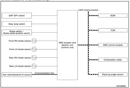
• The system switches fluid pressure of each brake caliper to increase, to hold or to decrease according to signals from control unit in ABS actuator and electric unit (control unit). This control system is applied to ESP function, TCS function, ABS function, EBD function and brake limited slip differential (BLSD) function.
• Fail-safe function is available for each function and is activated by each function when system malfunction occurs.
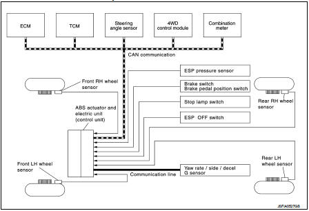
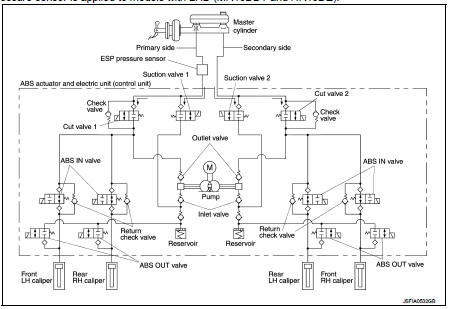
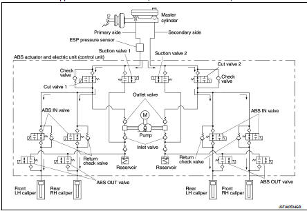
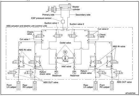
SYSTEM DIAGRAM
NOTE
:
• ESP pressure sensor is LHD models (MR16DDT and HR16DE) only.
• TCM is CVT models only.
• 4WD control module is 4WD models only.
INPUT SIGNAL AND OUTPUT SIGNAL
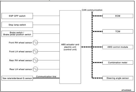
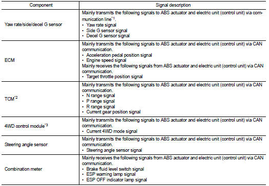
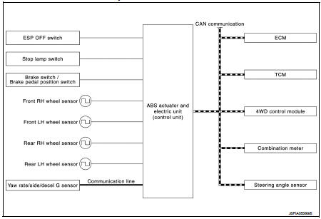
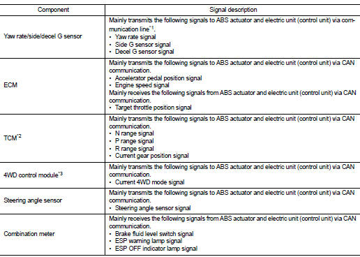
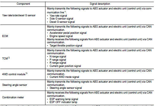
Major signal transmission between each unit via communication lines is shown in the following table.
ESP function, TCS function, ABS function, EBD function, Brake limited slip differential (BLSD) function
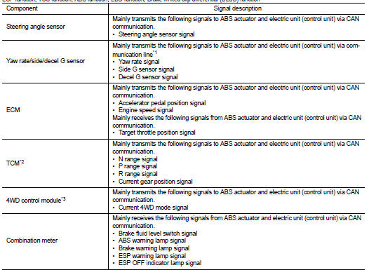
*1: Communication line between yaw rate/side/decel G sensor and ABS actuator
and electric unit (control unit)
*2: Models with CVT
*3: 4WD models
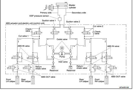
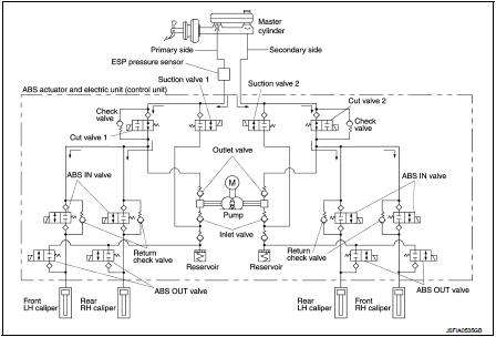
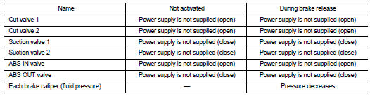
VALVE OPERATION [ESP FUNCTION, TCS FUNCTION AND BRAKE LIMITED SLIP DIFFERENTIAL (BLSD) FUNCTION
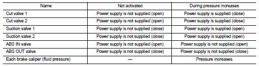
The control unit built in the ABS actuator and electric unit (control unit) controls fluid pressure of the brake calipers, respectively, by operating each valve.
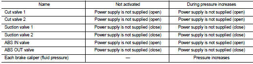
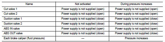
When ESP Function, TSC Function and Brake Limited Slip Differential (BLSD) Function is in Operation (During Pressure Increases) NOTE
:
ESP pressure sensor is applied to models with LHD (MR16DDT and HR16DE).
During pressure front RH brake caliper increases • Brake fluid is conveyed to the pump from the master cylinder through suction valve 2 and is pressurized by the pump operation. The pressurized brake fluid is supplied to the front RH brake caliper through the ABS IN valve. For the left caliper, brake fluid pressure is maintained because the pressurization is unnecessary. The pressurization for the left caliper is controlled separately from the right caliper.
During pressure front LH brake caliper increases • Brake fluid is conveyed to the pump from the master cylinder through suction valve 1 and is pressurized by the pump operation. The pressurized brake fluid is supplied to the front LH brake caliper through the ABS IN valve. For the right caliper, brake fluid pressure is maintained because the pressurization is unnecessary.
The pressurization for the right caliper is controlled separately from the left caliper.
During pressure rear RH brake caliper increases • Brake fluid is conveyed to the pump from the master cylinder through suction valve 1 and is pressurized by the pump operation. The pressurized brake fluid is supplied to the rear RH brake caliper through the ABS IN valve. For the left caliper, brake fluid pressure is maintained because the pressurization is unnecessary. The pressurization for the left caliper is controlled separately from the right caliper.
During pressure rear LH brake caliper increases • Brake fluid is conveyed to the pump from the master cylinder through suction valve 2 and is pressurized by the pump operation. The pressurized brake fluid is supplied to the rear LH brake caliper through the ABS INvalve. For the right caliper, brake fluid pressure is maintained because the pressurization is unnecessary.
The pressurization for the right caliper is controlled separately from the left caliper.
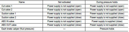
When ESP Function, TSC Function and Brake Limited Slip Differential (BLSD) Function is Starts Operating (During Pressure Holds) NOTE
:
ESP pressure sensor is applied to models with LHD (MR16DDT and HR16DE).
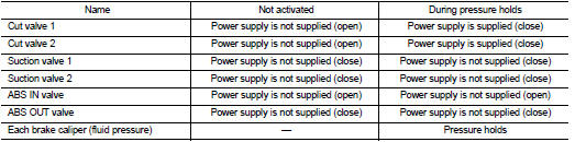
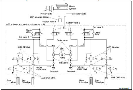
During pressure front RH brake caliper holds • Since the cut valve 2 and the suction valve 2 are closed, the front RH brake caliper, master cylinder, and reservoir are blocked. This maintains fluid pressure applied on the front RH brake caliper. The pressurization for the left caliper is controlled separately from the right caliper.
During pressure front LH brake caliper holds • Since the cut valve 1 and the suction valve 1 are closed, the front LH brake caliper, master cylinder, and reservoir are blocked. This maintains fluid pressure applied on the front LH brake caliper. The pressurization for the right caliper is controlled separately from the left caliper.
During pressure rear RH brake caliper holds • Since the cut valve 1 and the suction valve 1 are closed, the rear RH brake caliper, master cylinder, and reservoir are blocked. This maintains fluid pressure applied on the rear RH brake caliper. The pressurization for the left caliper is controlled separately from the right caliper.
During pressure rear LH brake caliper holds • Since the cut valve 2 and the suction valve 2 are closed, the rear LH brake caliper, master cylinder, and reservoir are blocked. This maintains fluid pressure applied on the rear LH brake caliper. The pressurization for the right caliper is controlled separately from the left caliper.
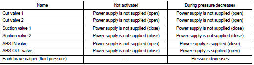
When ESP Function, TSC Function and Brake Limited Slip Differential (BLSD) Function is in Operation (During Pressure Decreases) NOTE
:
ESP pressure sensor is applied to models with LHD (MR16DDT and HR16DE).

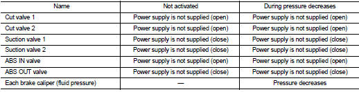
During pressure front RH brake caliper decreases • Since the suction valve 2 and the ABS OUT valve close and the cut valve 2 and the ABS IN valve open, the fluid pressure applied on the front RH brake caliper is reduced by supplying the fluid pressure to the master cylinder via the ABS IN valve and the cut valve 2. The pressurization for the right caliper is controlled separately from the left caliper.
During pressure front LH brake caliper decreases • Since the suction valve 1 and the ABS OUT valve close and the cut valve 1 and the ABS IN valve open, the fluid pressure applied on the front LH brake caliper is reduced by supplying the fluid pressure to the master cylinder via the ABS IN valve and the cut valve 2. The pressurization for the left caliper is controlled separately from the right caliper.
During pressure rear RH brake caliper decreases • Since the suction valve 1 and the ABS OUT valve close and the cut valve 1 and the ABS IN valve open, the fluid pressure applied on the rear RH brake caliper is reduced by supplying the fluid pressure to the master cylinder via the ABS IN valve and the cut valve 2. The pressurization for the right caliper is controlled separately from the left caliper.
During pressure rear LH brake caliper decreases • Since the suction valve 2 and the ABS OUT valve close and the cut valve 2 and the ABS IN valve open, the fluid pressure applied on the rear LH brake caliper is reduced by supplying the fluid pressure to the master cylinder via the ABS IN valve and the cut valve 2. The pressurization for the left caliper is controlled separately from the right caliper.
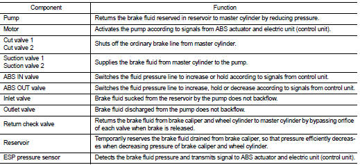
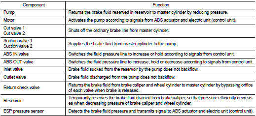
Component Parts and Function
VALVE OPERATION (ABS FUNCTION AND EBD FUNCTION)
The control unit built in the ABS actuator and electric unit (control unit) controls fluid pressure of the brake calipers, respectively, by operating each valve.
When Brake Pedal is Applied or ABS Function is in Operation (During Pressure Increases) NOTE
:
ESP pressure sensor is applied to models with LHD (MR16DDT and HR16DE)

During pressure front RH brake caliper increases • When the cut valve 2 and the ABS IN valve opens, brake fluid is supplied to the front RH brake caliper from the master cylinder through the ABS IN valve. Brake fluid does not flow into the reservoir because the ABS OUT valve is closed.
During pressure front LH brake caliper increases • When the cut valve 1 and the ABS IN valve opens, brake fluid is supplied to the front LH brake caliper from the master cylinder through the ABS IN valve. Brake fluid does not flow into the reservoir because the ABS OUT valve is closed.
During pressure rear RH brake caliper increases • When the cut valve 1 and the ABS IN valve opens, brake fluid is supplied to the rear RH brake caliper from the master cylinder through the ABS IN valve. Brake fluid does not flow into the reservoir because the ABS OUT valve is closed.
During pressure rear LH brake caliper increases • When the cut valve 2 and the ABS IN valve opens, brake fluid is supplied to the rear LH brake caliper from the master cylinder through the ABS IN valve. Brake fluid does not flow into the reservoir because the ABS OUT valve is closed.
When ABS Function is Starts Operating (During Pressure Holds)
NOTE
: ESP pressure sensor is applied to models with LHD (MR16DDT and HR16DE).
During pressure front RH brake caliper holds • Since the ABS IN valve and the ABS OUT valve are closed, the front RH brake caliper, master cylinder, and reservoir are blocked. This maintains fluid pressure applied on the front RH brake caliper.
During pressure front LH brake caliper holds • Since the ABS IN valve and the ABS OUT valve are closed, the front LH brake caliper, master cylinder, and reservoir are blocked. This maintains fluid pressure applied on the front LH brake caliper.
During pressure rear RH brake caliper holds • Since the ABS IN valve and the ABS OUT valve are closed, the rear RH brake caliper, master cylinder, and reservoir are blocked. This maintains fluid pressure applied on the rear RH brake caliper.
During pressure rear LH brake caliper holds • Since the ABS IN valve and the ABS OUT valve are closed, the rear LH brake caliper, master cylinder, and reservoir are blocked. This maintains fluid pressure applied on the rear LH brake caliper.
When ABS Function is in Operation (During Pressure Decreases)
NOTE
:
ESP pressure sensor is applied to models with LHD (MR16DDT and HR16DE).
During pressure front RH brake caliper decreases • Since the ABS IN valve is closed and the ABS OUT valve is opened, fluid pressure applied on the front RH brake caliper is supplied to the reservoir through the ABS OUT valve. This fluid pressure decreases when sent to the master cylinder by the pump.
During pressure front LH brake caliper decreases • Since the ABS IN valve is closed and the ABS OUT valve is opened, fluid pressure applied on the front LH brake caliper is supplied to the reservoir through the ABS OUT valve. This fluid pressure decreases when sent to the master cylinder by the pump.
During pressure rear RH brake caliper decreases • Since the ABS IN valve is closed and the ABS OUT valve is opened, fluid pressure applied on the rear RH brake caliper is supplied to the reservoir through the ABS OUT valve. This fluid pressure decreases when sent to the master cylinder by the pump.
During pressure rear LH brake caliper decreases • Since the ABS IN valve is closed and the ABS OUT valve is opened, fluid pressure applied on the rear LH brake caliper is supplied to the reservoir through the ABS OUT valve. This fluid pressure decreases when sent to the master cylinder by the pump.
When ABS Function is in Operation (During Pressure Increases)
NOTE
:
ESP pressure sensor is applied to models with LHD (MR16DDT and HR16DE).
During pressure front RH brake caliper increases • Brake fluid is supplied to the front RH brake caliper from the master cylinder through the cut valve 2 and the ABS IN valve. Since the suction valve 2 and the ABS OUT valve is closed, the fluid does not flow into the reservoir. The amount of brake fluid supplied to the front RH brake caliper from the master cylinder is controlled according to time that the ABS IN valve is not energized (time that the ABS IN valve is open).
During pressure front LH brake caliper increases • Brake fluid is supplied to the front LH brake caliper from the master cylinder through the cut valve 1 and the ABS IN valve. Since the suction valve 1 and the ABS OUT valve is closed, the fluid does not flow into the reservoir. The amount of brake fluid supplied to the front LH brake caliper from the master cylinder is controlled according to time that the ABS IN valve is not energized (time that the ABS IN valve is open).
During pressure rear RH brake caliper increases • Brake fluid is supplied to the rear RH brake caliper from the master cylinder through the cut valve 1 and the ABS IN valve. Since the suction valve 1 and the ABS OUT valve is closed, the fluid does not flow into the reservoir. The amount of brake fluid supplied to the rear RH brake caliper from the master cylinder is controlled according to time that the ABS IN valve is not energized (time that the ABS IN valve is open).
During pressure rear LH brake caliper increases • Brake fluid is supplied to the rear LH brake caliper from the master cylinder through the cut valve 2 and the ABS IN valve. Since the suction valve 2 and the ABS OUT valve is closed, the fluid does not flow into the reservoir. The amount of brake fluid supplied to the rear LH brake caliper from the master cylinder is controlled according to time that the ABS IN valve is not energized (time that the ABS IN valve is open).
When Brake Release
NOTE
:
ESP pressure sensor is applied to models with LHD (MR16DDT and HR16DE).
During front RH brake caliper release • Brake fluid is supplied to the front RH brake caliper through the return check valve of the ABS IN valve and the cut valve 2, and returns to the master cylinder.
During front LH brake caliper release • Brake fluid is supplied to the front LH brake caliper through the return check valve of the ABS IN valve and the cut valve 1, and returns to the master cylinder.
During rear RH brake caliper release • Brake fluid is supplied to the rear RH brake caliper through the return check valve of the ABS IN valve and the cut valve 1, and returns to the master cylinder.
During rear LH brake caliper release • Brake fluid is supplied to the rear LH brake caliper through the return check valve of the ABS IN valve and the cut valve 2, and returns to the master cylinder.
Component Parts and Function
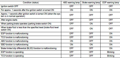
CONDITION FOR TURN ON THE WARNING LAMP
Turns ON when ignition switch turns ON and turns OFF when the system is normal, for bulb check purposes.
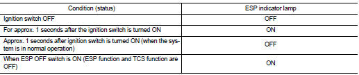
CONDITION FOR TURN ON THE INDICATOR LAMP
• Turns ON when ESP function and TCS function are switched to non-operational status (OFF) by ESP OFF switch.
• Turns ON when ignition switch turns ON and turns OFF when the system is normal, for bulb check purposes
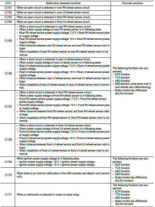
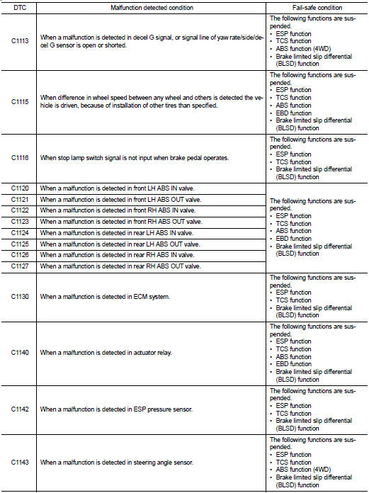
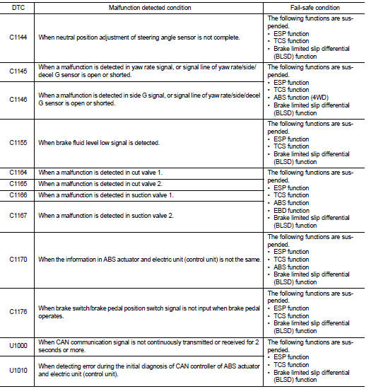
Fail-safe
ESP FUNCTION, TCS FUNCTION AND BRAKE LIMITED SLIP DIFFERENTIAL (BLSD) FUNCTION
ESP warning lamp in combination meter turn ON when a malfunction occurs in system [ABS actuator and electric unit (control unit)]. The control is suspended for ESP function, TCS function and brake limited slip differential (BLSD) function. The vehicle status becomes the same as models without ESP function, TCS function and brake limited slip differential (BLSD) function. However, ABS function and EBD function are operated normally.
ABS FUNCTION
ABS warning lamp and ESP warning lamp in combination meter turn ON when a malfunction occurs in system [ABS actuator and electric unit (control unit)]. The control is suspended for ESP function, TCS function, ABS function and brake limited slip differential (BLSD) function. The vehicle status becomes the same as models without ESP function, TCS function, ABS function and brake limited slip differential (BLSD) function. However, EBD function is operated normally.
NOTE
:
ABS self-diagnosis sound may be heard the same as in the normal condition,
because self-diagnosis is performed
when ignition switch turns ON and when vehicle initially starts.
EBD FUNCTION
ABS warning lamp, brake warning lamp and ESP warning lamp in combination meter turn ON when a malfunction occurs in system [ABS actuator and electric unit (control unit)]. The control is suspended for ESP function, TCS function, ABS function, EBD function and brake limited slip differential (BLSD) function. The vehicle status becomes the same as models without ESP function, TCS function, ABS function, EBD function and brake limited slip differential (BLSD) function.
ESP function : System Description
NOTE
:
ESP pressure sensor is applied to models with LHD (MR16DDT and HR16DE).
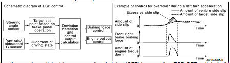
• Side slip or tail slip may occur while driving on a slippery road or intending an urgent evasive driving. ESP function detects side slip status using each sensor when side slip or tail slip is about to occur and improves vehicle stability by brake control and engine output control during driving.
• In addition to ABS function, EBD function and TCS function, target side slip amount is calculated according to steering operation amount from steering angle sensor. By comparing this information with vehicle side slip amount that is calculated from information from yaw rate/side/decel G sensor and wheel sensor, vehicle driving conditions (conditions of understeer or oversteer) are judged and vehicle stability is improved by brake force control on all 4 wheels and engine output control.
• ESP function can be switched to non-operational status (OFF) by operating ESP OFF switch. In this case, ESP OFF indicator lamp turns ON.
• Control unit portion automatically improves driving stability by performing brake force control as well as engine output control, by transmitting drive signal to actuator portion according to difference between target side slip amount and vehicle side slip amount • ESP warning lamp blinks while ESP function is in operation and indicates to the driver that the function is in operation.
• CONSULT-III can be used to diagnose the system diagnosis.
• Fail-safe function is adopted. When a malfunction occurs in ESP function, the control is suspended for ESP function, TCS function and brake limited slip differential (BLSD) function. The vehicle status becomes the same as models without ESP function, TCS function and brake limited slip differential (BLSD) function. However, ABS function and EBD function are operated normally. Refer to BRC-117, "Fail-safe".
NOTE
:
ESP has the characteristic as described here, This is not the device that helps
reckless driving.
SYSTEM DIAGRAM
NOTE
:
• TCM is CVT models only.
• 4WD control module is 4WD models only.
INPUT SIGNAL AND OUTPUT SIGNAL
Major signal transmission between each unit via communication lines is shown in the following table.
*1: Communication line between yaw rate/side/decel G sensor and ABS actuator
and electric unit (control unit)
*2: Models with CVT
*3: 4WD models
OPERATION CHARACTERISTICS
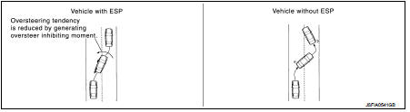
ESP Function That Prevents Oversteer Tendency • During a cornering, brake force (brake fluid pressure) is applied on front wheel and rear wheel on the outer side of turn. Moment directing towards the outer side of turn is generated. Oversteer is prevented.
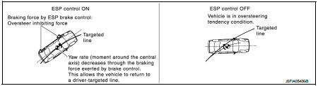
• Changing driving lane on a slippery road, when oversteer tendency is judged large, engine output is controlled as well as brake force (brake fluid pressure) of 4 wheels. Oversteer tendency decreases.
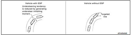
ESP Function That Prevents Understeer Tendency • During a cornering, brake force (brake fluid pressure) is applied on front wheel and rear wheel on the inner side of turn. Moment directing towards the inner side of turn is generated. Understeer is prevented.
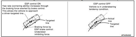
• Applying braking during a cornering on a slippery road, when understeer tendency is judged large, engine output is controlled as well as brake force (brake fluid pressure) of four wheels. Understeer tendency decreases.
TCS function: System Description
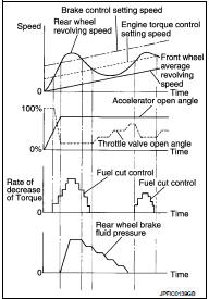
• Wheel spin status of drive wheel is detected by wheel sensor of 4 wheels. Engine output and transmission shift status is controlled so that slip rate of drive wheels is in appropriate level. When wheel spin occurs on drive wheel, ABS actuator and electric unit (control unit) perform brake force control of LH and RH drive wheels (apply brake force by increasing brake fluid pressure of drive wheel) and decrease engine torque by engine torque control. Wheel spin amount decreases. Engine torque is controlled to appropriate level.
• TCS function can be switched to non-operational status (OFF) by operating ESP OFF switch. In this case, ESP OFF indicator lamp turns ON.
• ESP warning lamp blinks while TCS function is in operation and indicates to the driver that the function is in operation.
• CONSULT-III can be used to diagnose the system diagnosis.
• Fail-safe function is adopted. When a malfunction occurs in TCS function, the control is suspended for ESP function, TCS function and brake limited slip differential (BLSD) function. The vehicle status becomes the same as models without ESP function, TCS function and brake limited slip differential (BLSD) function. However, ABS function and EBD function are operated normally. Refer to BRC-117, "Fail-safe".
SYSTEM DIAGRAM
NOTE
:
• TCM is CVT models only.
• 4WD control module is 4WD models only.
INPUT SIGNAL AND OUTPUT SIGNAL
Major signal transmission between each unit via communication lines is shown in the following table.
*1: Communication line between yaw rate/side/decel G sensor and ABS actuator
and electric unit (control unit)
*2: Models with CVT
*3: 4WD models
ABS function : System Description
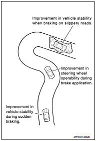
• By preventing wheel lock through brake force (brake fluid pressure) control that is electronically controlled by detecting wheel speed during braking, stability during emergency braking is improved so that obstacles can be easily bypassed by steering operation.
• During braking, control units calculates wheel speed and pseudo-vehicle speed, and transmits pressure increase, hold or decrease signals to actuator portion according to wheel slip status.
• The following effects are obtained by preventing wheel lock during braking.
- Vehicle tail slip is prevented during braking when driving straight.
- Understeer and oversteer tendencies are moderated during braking driving on a corner.
- Obstacles may be easily bypassed by steering operation during braking.
• CONSULT-III can be used to diagnose the system diagnosis.
• Fail-safe function is adopted. When a malfunction occurs in ABS function, the control is suspended for ESP function, TCS function, ABS function and brake limited slip differential (BLSD) function.
The vehicle status becomes the same as models without ESP function, TCS function, ABS function and brake limited slip differential (BLSD) function. However, EBD function is operated normally.
Refer to BRC-117, "Fail-safe".
NOTE
:
• ABS has the characteristic as described here, but it is not the
device that helps reckless driving.
• To stop vehicle efficiently, ABS does not operate and ordinary brake operates at low speed [approx. 5 to 10 km/h (3.1 to 6.2 MPH) or less, but differs subject to road conditions).
• Self-diagnosis is performed immediately after when engine starts and when vehicle initially is driven [by vehicle speed approx. 15 km/h (9.3 MPH)]. Motor sounds are generated during self-diagnosis.
In addition, brake pedal may be felt heavy when depressing brake pedal lightly. These symptoms are not malfunctions.
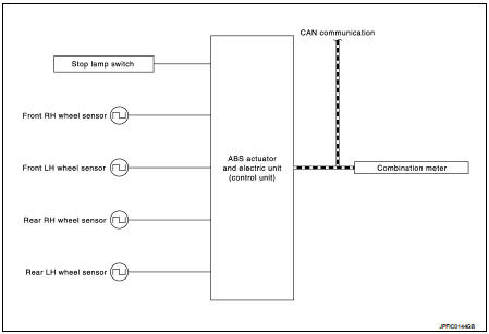
SYSTEM DIAGRAM
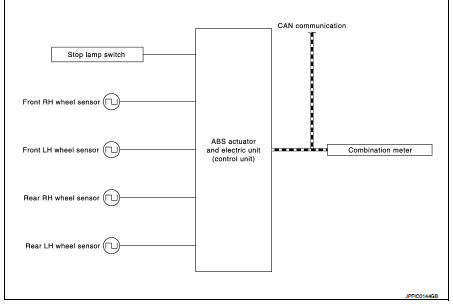
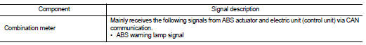
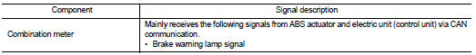
INPUT SIGNAL AND OUTPUT SIGNAL
Major signal transmission between each unit via communication lines is shown in the following table.
EBD function : System Description
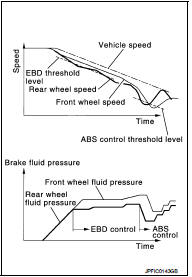
• By preventing rear wheel slip increase through rear wheel brake force (brake fluid pressure) control that is electronically controlled when slight skip on front and rear wheels are detected during braking, stability during braking is improved.
• EBD function is expanded and developed from conventional ABS function and corrects rear wheel brake force to appropriate level by electronic control according to load weight (number of passengers).
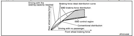
• During braking, control unit portion compares slight slip on front and rear wheels by wheel speed sensor signal, transmits drive signal to actuator portion when rear wheel slip exceeds front wheel slip for the specified value or more, and controls rear wheel brake force (brake fluid pressure) so that increase of rear wheel slip is prevented and slips on front wheel and rear wheel are nearly equalized. ABS control is applied when slip on each wheel increases and wheel speed is the threshold value of ABS control or less.
• CONSULT-III can be used to diagnose the system diagnosis.
• Fail-safe function is adopted. When a malfunction occurs in EBD function, the control is suspended for ESP function, TCS function, ABS function, EBD function and brake limited slip differential (BLSD) function. The vehicle status becomes the same as models without ESP function, TCS function, ABS function, EBD function and brake limited slip differential (BLSD) function. Refer to BRC- 117, "Fail-safe".
SYSTEM DIAGRAM
INPUT SIGNAL AND OUTPUT SIGNAL
Major signal transmission between each unit via communication lines is shown in the following table.
Brake limited slip differential (blsd) function : System Description
• LH and RH driving wheel spin is always monitored. If necessary, appropriate brake force is independently applied to LH or RH driving wheel so that one-sided wheel spin is avoided and traction is maintained. Mainly starting ability is improved.
• Brake limited slip differential (BLSD) function operates while ESP function is in non-operational status (OFF) by ESP OFF switch.
• ESP warning lamp blinking while brake limited slip differential (BLSD) function is in operation and indicates to the driver that the function is in operation.
• Slight vibrations are felt on the brake pedal and the operation noises occur, when brake limited slip differential (BLSD) function operates. This is not a malfunction because it is caused by brake limited slip differential (BLSD) function that is normally operated.
• Fail-safe function is adopted. When a malfunction occurs in brake limited slip differential (BLSD) function, the control is suspended for ESP function, TCS function and brake limited slip differential (BLSD) function.
The vehicle status becomes the same as models without ESP function, TCS function and brake limited slip differential (BLSD) function. However, ABS function and EBD function are operated normally. Refer to BRC- 117, "Fail-safe".
SYSTEM DIAGRAM
NOTE
:
• TCM is CVT models only.• 4WD control module is 4WD models only.
• 4WD control module is 4WD models only.
INPUT SIGNAL AND OUTPUT SIGNAL
Major signal transmission between each unit via communication lines is shown in the following table.
*1: Communication line between yaw rate/side/decal G sensor and ABS actuator
and electric unit (control unit)
*2: Models with CVT
*3: 4WD models
 Component parts
Component Parts Location
LHD
2WD
1. ECM
Refer to EC-25, "ENGINE CONTROL
SYSTEM :
Component Parts Location"
(MR16DDT), EC-455, "ENGINE
CONTROL SYSTEM :
Component Parts Locatio ...
 Diagnosis system [ABS actuator and electric unit (control
unit)]
Diagnosis system [ABS actuator and electric unit (control
unit)]
CONSULT-III Function
APPLICATION ITEMS
CONSULT-III can display each diagnostic item using the diagnostic test modes
as follows.
*1: The following diagnosis information is erased by erasing.
• ...
Other materials:
Basic inspection
DIAGNOSIS AND REPAIR WORK FLOW
Work Flow
DETAILED FLOW
1.OBTAIN INFORMATION ABOUT SYMPTOM
Interview the customer to obtain the malfunction information (conditions and
environment when the malfunction
occurred) as much as possible when the customer brings the vehicle in.
>> GO TO 2.
...
P0607 ECM
DTC Logic
DTC DETECTION LOGIC
DTC CONFIRMATION PROCEDURE
1.PERFORM DTC CONFIRMATION PROCEDURE
1. Turn ignition switch ON.
2. Check DTC.
Is DTC detected?
YES >> Proceed to EC-304, "Diagnosis Procedure".
NO >> INSPECTION END
Diagnosis Procedur
1.INSPECTION START
...
Periodic maintenance
Periodic Maintenance
The following tables show the normal maintenance schedule. Depending upon
weather and atmospheric conditions,
varying road surfaces, individual driving habits and vehicle usage, additional
or more frequent maintenance
may be required.
Periodic maintenance beyond the la ...
