Nissan Juke Service and Repair Manual : System
System Description
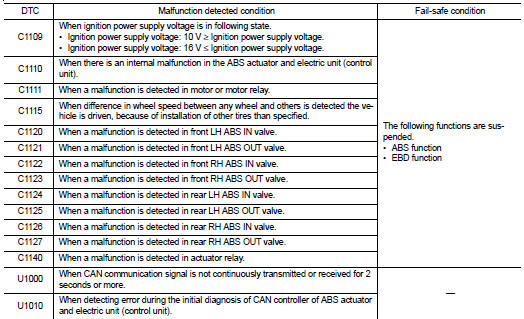
• The system switches fluid pressure of each brake caliper to increase, to hold or to decrease according to signals from control unit in ABS actuator and electric unit (control unit). This control system is applied to ABS function and EBD function.
• Fail-safe function is available for each function and is activated by each function when system malfunction occurs.
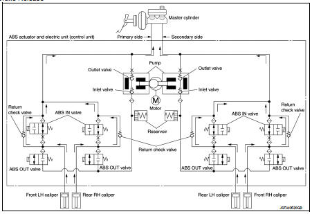
SYSTEM DIAGRAM
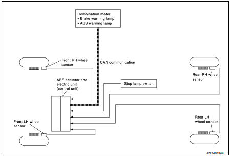
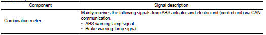
INPUT SIGNAL AND OUTPUT SIGNAL
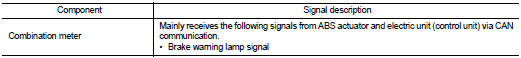
Major signal transmission between each unit via communication lines is shown in the following table.
ABS function, EBD function
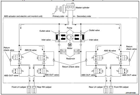
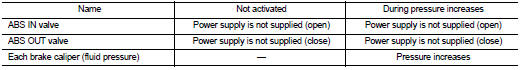
VALVE OPERATION
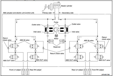
The control unit built in the ABS actuator and electric unit (control unit) controls fluid pressure of the brake calipers, respectively, by operating each valve.
When Brake Pedal is Applied or ABS is in Operation (During Pressure Increases)
During pressure front RH brake caliper increases • When the ABS IN valve opens, brake fluid is supplied to the front RH brake caliper from the master cylinder through the ABS IN valve. Brake fluid does not flow into the reservoir because the ABS OUT valve is closed.
During pressure front LH brake caliper increases • When the ABS IN valve opens, brake fluid is supplied to the front LH brake caliper from the master cylinder through the ABS IN valve. Brake fluid does not flow into the reservoir because the ABS OUT valve is closed.
During pressure rear RH brake caliper increases • When the ABS IN valve opens, brake fluid is supplied to the rear RH brake caliper from the master cylinder through the ABS IN valve. Brake fluid does not flow into the reservoir because the ABS OUT valve is closed.
During pressure rear LH brake caliper increases • When the ABS IN valve opens, brake fluid is supplied to the rear LH brake caliper from the master cylinder through the ABS IN valve. Brake fluid does not flow into the reservoir because the ABS OUT valve is closed.
When ABS is Starts Operating (During Pressure Holds)
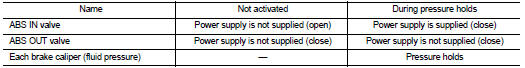
During pressure front RH brake caliper holds • Since the ABS IN valve and the ABS OUT valve are closed, the front RH brake caliper, master cylinder, and reservoir are blocked. This maintains fluid pressure applied on the front RH brake caliper.
During pressure front LH brake caliper holds • Since the ABS IN valve and the ABS OUT valve are closed, the front LH brake caliper, master cylinder, and reservoir are blocked. This maintains fluid pressure applied on the front LH brake caliper.
During pressure rear RH brake caliper holds • Since the ABS IN valve and the ABS OUT valve are closed, the rear RH brake caliper, master cylinder, and reservoir are blocked. This maintains fluid pressure applied on the rear RH brake caliper.
During pressure rear LH brake caliper holds • Since the ABS IN valve and the ABS OUT valve are closed, the rear LH brake caliper, master cylinder, and reservoir are blocked. This maintains fluid pressure applied on the rear LH brake caliper.
When ABS is in Operation (During Pressure Decreases)
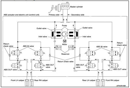
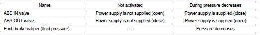
During pressure front RH brake caliper decreases • Since the ABS IN valve is closed and the ABS OUT valve is opened, fluid pressure applied on the front RH brake caliper is supplied to the reservoir through the ABS OUT valve. This fluid pressure decreases when sent to the master cylinder by the pump.
During pressure front LH brake caliper decreases • Since the ABS IN valve is closed and the ABS OUT valve is opened, fluid pressure applied on the front LH brake caliper is supplied to the reservoir through the ABS OUT valve. This fluid pressure decreases when sent to the master cylinder by the pump.
During pressure rear RH brake caliper decreases • Since the ABS IN valve is closed and the ABS OUT valve is opened, fluid pressure applied on the rear RH brake caliper is supplied to the reservoir through the ABS OUT valve. This fluid pressure decreases when sent to the master cylinder by the pump.
During pressure rear LH brake caliper decreases • Since the ABS IN valve is closed and the ABS OUT valve is opened, fluid pressure applied on the rear LH brake caliper is supplied to the reservoir through the ABS OUT valve. This fluid pressure decreases when sent to the master cylinder by the pump.
When ABS is in Operation (During Pressure Increases)

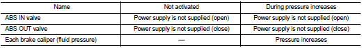
During pressure front RH brake caliper increases • Brake fluid is supplied to the front RH brake caliper from the master cylinder through the ABS IN valve. Since the ABS OUT valve is closed, the fluid does not flow into the reservoir. The amount of brake fluid supplied to the front RH brake caliper from the master cylinder is controlled according to time that the ABS IN valve is not energized (time that the ABS IN valve is open).
During pressure front LH brake caliper increases • Brake fluid is supplied to the front LH brake caliper from the master cylinder through the ABS IN valve. Since the ABS OUT valve is closed, the fluid does not flow into the reservoir. The amount of brake fluid supplied to the front LH brake caliper from the master cylinder is controlled according to time that the ABS IN valve is not energized (time that the ABS IN valve is open).
During pressure rear RH brake caliper increases • Brake fluid is supplied to the rear RH brake caliper from the master cylinder through the ABS IN valve. Since the ABS OUT valve is closed, the fluid does not flow into the reservoir. The amount of brake fluid supplied to the rear RH brake caliper from the master cylinder is controlled according to time that the ABS IN valve is not energized (time that the ABS IN valve is open).
During pressure rear LH brake caliper increases • Brake fluid is supplied to the rear LH brake caliper from the master cylinder through the ABS IN valve. Since the ABS OUT valve is closed, the fluid does not flow into the reservoir. The amount of brake fluid supplied to the rear LH brake caliper from the master cylinder is controlled according to time that the ABS IN valve is not energized (time that the ABS IN valve is open).
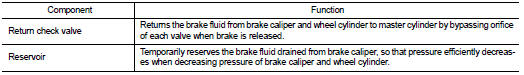
When Brake Release
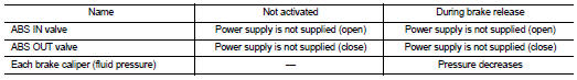
During front RH brake caliper release • Brake fluid is supplied to the front RH brake caliper through the return check valve of the ABS IN valve and returns to the master cylinder.
During front LH brake caliper release • Brake fluid is supplied to the front LH brake caliper through the return check valve of the ABS IN valve and returns to the master cylinder.
During rear RH brake caliper release • Brake fluid is supplied to the rear RH brake caliper through the return check valve of the ABS IN valve and returns to the master cylinder.
During rear LH brake caliper release • Brake fluid is supplied to the rear LH brake caliper through the return check valve of the ABS IN valve and returns to the master cylinder.
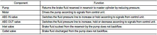
Component Parts and Function
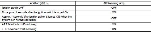
CONDITION FOR TURN ON THE WARNING LAMP
ABS Warning Lamp
• Turns ON when either ABS function or EBD function is malfunctioning.
• Turns ON when ignition switch turns ON and turns OFF when the system is normal, for bulb check purposes.
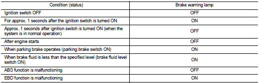
Brake Warning Lamp
• Turns ON when EBD function is malfunctioning.
• Turns ON when ignition switch turns ON and turns OFF when the system is normal, for bulb check purposes.
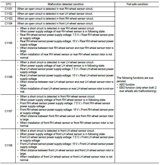
Fail-safe
ABS FUNCTION
ABS warning lamp in combination meter turn ON when a malfunction occurs in system [ABS actuator and electric unit (control unit)]. The control is suspended for ABS function. The vehicle status becomes the same as models without ABS function. However, EBD function is operated normally.
NOTE
:
ABS self-diagnosis sound may be heard the same as in the normal condition,
because self-diagnosis is performed
when ignition switch turns ON and when vehicle initially starts.
EBD FUNCTION
ABS warning lamp and brake warning lamp in combination meter turn ON when a malfunction occurs in system [ABS actuator and electric unit (control unit)]. The control is suspended for ABS function and EBD function.
The vehicle status becomes the same as models without ABS function and EBD function.
ABS function : System Description
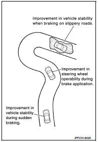
• By preventing wheel lock through brake force (brake fluid pressure) control that is electronically controlled by detecting wheel speed during braking, stability during emergency braking is improved so that obstacles can be easily bypassed by steering operation.
• During braking, control units calculates wheel speed and pseudo-vehicle speed, and transmits pressure increase, hold or decrease signals to actuator portion according to wheel slip status.
• The following effects are obtained by preventing wheel lock during braking.
- Vehicle tail slip is prevented during braking when driving straight.
- Understeer and oversteer tendencies are moderated during braking driving on a corner.
- Obstacles may be easily bypassed by steering operation during braking.
• CONSULT-III can be used to diagnose the system diagnosis.
• Fail-safe function is adopted. When a malfunction occurs in ABS function, the control is suspended for ABS function. The vehicle status becomes the same as models without ABS function. However, EBD function is operated normally. Refer to BRC-19, "Failsafe".
NOTE
:
• ABS has the characteristic as described here, but it is not the
device that helps reckless driving.
• To stop vehicle efficiently, ABS does not operate and ordinary brake operates at low speed [approx. 5 to 10 km/h (3.1 to 6.2 MPH) or less, but differs subject to road conditions).
• Self-diagnosis is performed immediately after when engine starts and when vehicle initially is driven [by vehicle speed approx. 15 km/h (9.3 MPH)]. Motor sounds are generated during self-diagnosis.
In addition, brake pedal may be felt heavy when depressing brake pedal lightly. These symptoms are not malfunctions.
SYSTEM DIAGRAM

INPUT SIGNAL AND OUTPUT SIGNAL
Major signal transmission between each unit via communication lines is shown in the following table.
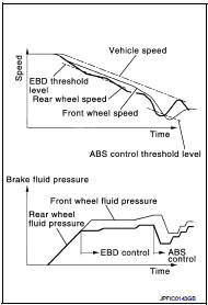
EBD function : System Description
• By preventing rear wheel slip increase through rear wheel brake force (brake fluid pressure) control that is electronically controlled when slight skip on front and rear wheels are detected during braking, stability during braking is improved.
• EBD function is expanded and developed from conventional ABS function and corrects rear wheel brake force to appropriate level by electronic control according to load weight (number of passengers).
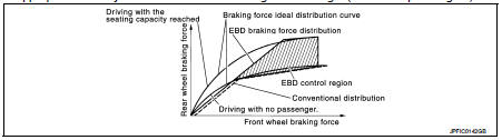
• During braking, control unit portion compares slight slip on front and rear wheels by wheel speed sensor signal, transmits drive signal to actuator portion when rear wheel slip exceeds front wheel slip for the specified value or more, and controls rear wheel brake force (brake fluid pressure) so that increase of rear wheel slip is prevented and slips on front wheel and rear wheel are nearly equalized. ABS control is applied when slip on each wheel increases and wheel speed is the threshold value of ABS control or less.
• CONSULT-III can be used to diagnose the system diagnosis.
• Fail-safe function is adopted. When a malfunction occurs in EBD function, the control is suspended for ABS function and EBD function.
The vehicle status becomes the same as models without ABS function and EBD function. Refer to BRC-19, "Fail-safe".
SYSTEM DIAGRAM
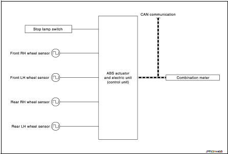
INPUT SIGNAL AND OUTPUT SIGNAL
Major signal transmission between each unit via communication lines is shown in the following table.
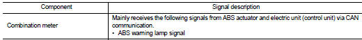
 Component parts
Component Parts Location
LHD
1. ABS actuator and electric unit (control
unit)
2. Front wheel sensor
3. Stop lamp switch
4. Rear wheel sensor
A. Inside engine room
B. Steering knuckle
C. ...
 Diagnosis system [ABS actuator and electric unit (control
unit)]
Diagnosis system [ABS actuator and electric unit (control
unit)]
CONSULT-III Function
APPLICATION ITEMS
CONSULT-III can display each diagnostic item using the diagnostic test modes
as follows.
*: The following diagnosis information is erased by erasing.
• ...
Other materials:
Heavy tight-corner braking symptom occurs
Description
Heavy tight-corner braking symptom occurs when the vehicle is driven and the
steering wheel is turned fully to
either side after the engine is started.
NOTE:
Light tight-corner braking symptom may occur depending on driving conditions.
This is not malfunction.
Diagnosis Proced ...
HR16DE : Inspection and Adjust
INSPECTION
Magnetic Switch Check
• Before starting to check, disconnect the battery cable from the negative
terminal.
• Disconnect “M” terminal of starter motor.
1. Continuity test [between “S” terminal (A) and switch body]
B : “B” terminal
C : “M” terminal
• Replace magnetic switch if co ...
Fuel-filler cap
To remove the fuel-filler cap:
1. Turn the fuel-filler cap counterclockwise 1 to remove.
2. Put the fuel-filler cap on the cap holder A while refueling.
To install the fuel-filler cap:
1. Insert the fuel-filler cap straight into the fuelfiller tube.
2. Turn the fuel-filler cap clockwise 2 unt ...
