Nissan Juke Service and Repair Manual : System
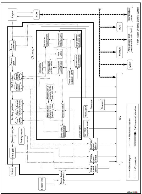
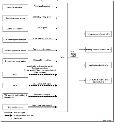
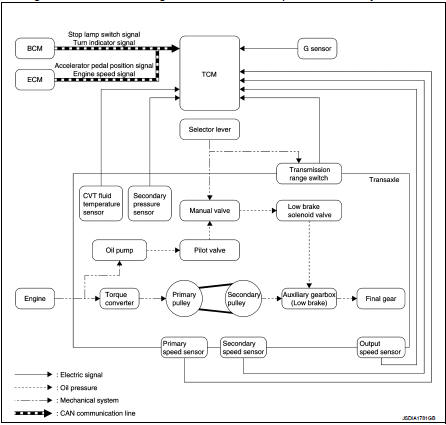
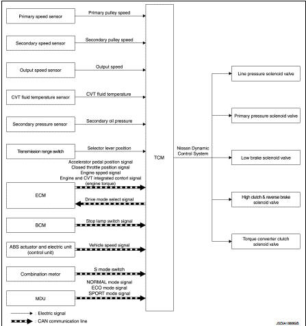
CVT control system : System Diagram
CVT control system : System Description
The CVT senses vehicle operating conditions through various sensors. It always controls the optimum shift position and reduces shifting and lock-up shocks.
TCM FUNCTION
The function of the TCM is to: • Receive input signals sent from various switches and sensors.
• Determine required line pressure, shifting point, and lock-up operation.
• Send required output signals to the step motor and the respective solenoids.
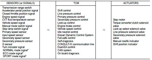
*: With Nissan Dynamic Control System
INPUT/OUTPUT SIGNAL OF TCM
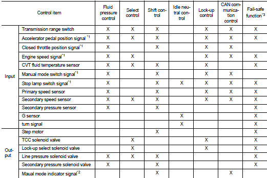
*1: Input via CAN communications.
*2: Output via CAN communications.
*3: If these input and output signals are different, the TCM triggers the fail-safe function.
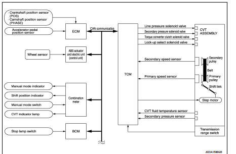
CVT control system : System Diagram
CVT control system : Fail-safe
The TCM has an electrical fail-safe mode. In this mode TCM is operator even if there is an error in a main electronic control input/output signal circuit.
Description When a malfunction is detected in each sensor, switch, solenoid or others, this function provides control to minimize reduction of drivability so that durability of transmission assembly can be acquired.
Line pressure control : System Diagram
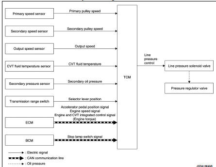
Line pressure control : System Description
Highly accurate line pressure control (secondary pressure control) reduces friction for improvement of fuel economy.
NORMAL OIL PRESSURE CONTROL
Appropriate line pressure and secondary pressure suitable for driving condition are determined based on the accelerator pedal position, engine speed, primary pulley (input) speed, secondary pulley (output) speed, vehicle speed, input torque, stop lamp switch signal, transmission range switch signal, lock-up signal, power voltage, target shift ratio, oil temperature and oil pressure.
SECONDARY PRESSURE FEEDBACK CONTROL
In normal oil pressure control and oil pressure control in shifting, highly accurate secondary pressure is determined by detecting the secondary pressure using a oil pressure sensor and by feedback control.
Shift change control : System Diagram
Shift change control : System Description
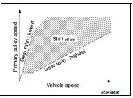
To select the gear ratio that can give the driving force to meet driver's intent or vehicle situation, the vehicle driving condition such as vehicle speed or accelerator pedal position is detected and the most appropriate gear ratio is selected and the shifting method before reaching the speed is determined. The information is output to the primary pressure solenoid valve to control the line pressure input/output to the primary pulley, to determine the primary pulley (movable pulley) position and to control the gear position.
D POSITION
Gear shifting is performed in all shifting ranges from the lowest to the highest gear ratio.
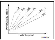
“M” POSITION
When the selector lever is put in the manual shift gate side, the fixed changing gear line is set. By moving the selector lever to + side or – side, the manual mode switch is changed over, and shift change like M/T becomes possible following the changing gear set line step by step..
MANUAL MODE INFOMATION
The TCM transmits the manual mode shift refusal signal to the combination meter if the TCM refuses the transmission from the driving status of vehicle when the selector lever or paddle shifter shifts to “UP (+ side)” or “DOWN (– side)” side. The combination meter blinks shift indicator on the combination meter and sounds the buzzer to indicate the driver that the shifting is not performed when receiving this signal. However, the TCM does not transmit the manual mode shift refusal signal in the conditions as per the following..
• When the selector lever or the paddle shifter shifts to “DOWN (– side)” side while driving in M1.
• When the selector lever or the paddle shifter shifts to “UP (+ side)” side while driving in M6.
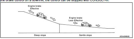
HILL CLIMBING AND DESCENDING CONTROL
If a downhill is detected with the accelerator pedal is released, the system performs downshift to increase the engine brake force so that vehicle may not be accelerated more than necessary. If a climbing hill is detected, the system improves the acceleration performance in re-acceleration by limiting the gear shift range on the high side.
NOTE: For engine brake control on a downhill, the control can be stopped with CONSULT-III.
CONTROL IN ACCELERATION
From change of the vehicle speed or accelerator pedal position, the acceleration request level of the driver or driving scene is evaluated. In start or acceleration during driving, the gear shift characteristics with linearity of revolution increase and vehicle speed increase are gained to improve the acceleration feel.
Select control : System diagram
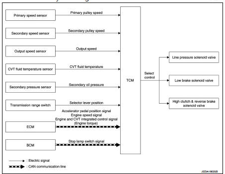
Select control : System Description
Based on accelerator pedal angle, engine speed, primary pulley speed, and the secondary pulley speed, the optimum operating pressure is set to reduce impact of a selector lever operation while shifting from “N” (“P”) to “D” (“R”) position.
Lock-up control : System Diagram
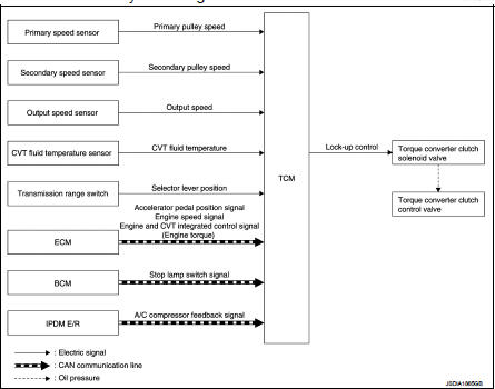
Lock-up control : System Description
• Controls for improvement of the transmission efficiency by engaging the torque converter clutch in the torque converter and eliminating slip of the converter. Achieves comfortable driving with slip control of the torque converter clutch.
• The oil pressure feed circuit for the torque converter clutch piston chamber is connected to the torque converter clutch control valve. The torque converter clutch control valve is switched by the torque converter clutch solenoid valve with the signal from TCM. This controls the oil pressure circuit, which is supplied to the torque converter clutch piston chamber, to the release side or engagement side.
• If the CVT fluid temperature is low or the vehicle is in fail-safe mode due to malfunction, lock-up control is prohibited.
Lock-up engagement
• In lock-up engagement, the torque converter clutch solenoid valve makes the
torque converter clutch control
valve locked up to generate the lock-up apply pressure. This pushes the torque
converter clutch piston for
engagement.
Lock-up release condition • In lock-up release, the torque converter clutch solenoid valve makes the torque converter clutch control valve non-locked up to drain the lock-up apply pressure. This does not engage the torque converter clutch piston.
Idle neutral control : System Diagram
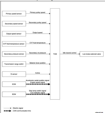
Idle neutral control : System Description
If a driver has no intention of starting the vehicle in D position, TCM operates the low brake solenoid valve and controls the oil pressure of the low brake to be low pressure. Therefore, the low brake is in the release (slip) status and the power transmission route of transaxle is the same status as the N position. In this way, the transaxle is in idling status and load to the engine can be reduced to improve fuel economy.
IDLE NEUTRAL CONTROL START CONDITION
Idle neutral control is started when all of the following conditions are fulfilled. However, during idle neutral control, idle neutral control is stopped when any of the following conditions is not met.
Driving environment : Flat road or road with mild gradient
Selector lever position : “D” position
Vehicle speed : 0 km/h (0 MPH)
Accelerator pedal position : 0.0/8
Brake pedal : Depressed
Engine speed : Idle speed
Turn signal lamp/hazard signal lamp : Not activate
NOTE
:
Stops or prohibits the idle neutral control when the TCM and ECM detect that the
vehicle is in one of the following
conditions.
• Engine coolant temperature and CVT fluid temperature are the specified temperature or more, or the specified temperature or less.
• When a transaxle malfunction occurs.
• When the vehicle detects DTC and is in the fail-safe mode.
IDLE NEUTRAL CONTROL RESUME CONDITION
When the idle neutral control finishes, if the vehicle is driven at more than the specified speed and the idle neutral control start conditions are satisfied, the idle neutral control starts again. If the vehicle has a malfunction, the idle neutral control does not start.
Lock-up and select control system : System diagram
Lock-up and select control system : System Description
• TCM receives the NORMAL mode signal, ECO mode signal or SPORT mode signal from the multi display unit through CAN communication.
• TCM sends the recognized control mode to ECM through CAN communication (drive mode select signal).
• With operation on the multi display unit, the mode is changed on the display, but the mode is actually not changed due to CAN communication malfunction.
• The gear shift line is not changed with the control mode change for the
following conditions:
- When the selector lever is at “L” position.
- When the selector lever is at “D” position and S mode is ON.
CONTROL DETAILS OF EACH MODE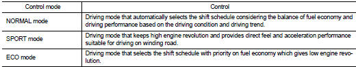
FAIL-SAFE
If CAN communication malfunction occurs between TCM and the multi display unit, the mode when the malfunction occurs is maintained for approximately 30 seconds and the mode is changed to NORMAL mode when the accelerator pedal is released.
Shift lock system : System Descripti
• The shift lock is the mechanism provided to prevent quick start of a vehicle by incorrect operation of a drive when the selector lever is in P position.
• Selector lever can be shifted from the P position to another position when the following conditions are satisfied.
- Ignition switch is ON.
- Stop lamp switch ON (brake pedal is depressed) - Press the selector button.
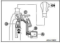
SHIFT LOCK OPERATION AT P POSITION
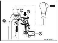
When brake pedal is not depressed (no selector operation allowed) When the brake pedal is not depressed with the ignition switch ON, the shift lock solenoid (A) is OFF (not energized) and the solenoid rod (B) is extended with spring.
The connecting lock lever (C) is located at the position shown in the figure when the solenoid rod is extended. It prevents the movement of the detent rod (D). The selector lever cannot be shifted from the P position for this reason.
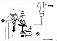
When brake pedal is depressed (selector lever operation allowed) The shift lock solenoid (A) is turned ON (energized) when the brake pedal is depressed with the ignition switch ON. The solenoid rod (B) is compressed with the electromagnetic force. The connecting lock lever (C) rotates when the solenoid rod is compressed. Therefore, the detent rod (D) can be moved. The selector lever can be shifted to other positions for this reason.
P POSITION HOLD MECHANISM (IGNITION SWITCH LOCK)
The shift lock solenoid (1) is not energized when the ignition switch is in any position other than ON. The shift mechanism is locked and P position is held. The operation cannot be performed from P position if the brake pedal is depressed with the ignition switch ON when the operation system of shift lock solenoid (1) is malfunctioning.
However, the lock lever (A) is forcibly rotated and the shift lock is released when the shift lock release button (A) is pressed from above. The selector operation from P position can be performed.
CAUTION:
Use the shift lock release button only when the selector lever
cannot be operated even if the brake pedal is depressed with
the ignition switch ON.
Key lock system : System Description
KEY LOCK MECHANISM
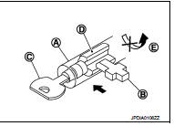
The key is not set to LOCK when the selector lever is not selected to P position. This prevents the key from being removed from the key cylinder.
Key lock status
The slider (B) in the key cylinder (A) is moved to the left side of the
figure when the selector lever is in any position other than P position.
The rotator (D) that rotates together with the key (C) cannot be rotated for this reason. The key cannot be removed from the key cylinder because it cannot be turned to LOCK (E).
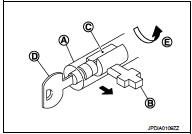
Key unlock status
The slider (B) in the key cylinder (A) is moved to the right side of the
figure when the selector lever is in P position and the finger is
removed from the selector button. The rotator (C) can be rotated for
this reason. The key (D) can be removed from the key cylinder
because it can be turned to LOCK (E).
 Structure and operation
Transaxle : Cross-Sectional View
1. Converter housing
2. Driven sprocket
3. Chain
4. Reverse brake
5. Oil pump
6. Forward clutch
7. Planetary carrier
8. Primary pulley
9. Sun gear
10 ...
 On board diagnostic (OBD) system
Diagnosis Description
DESCRIPTION
The CVT system has two self-diagnostic systems.
The first is the emission-related on board diagnostic system (OBD) performed by
the TCM in combination with
th ...
Other materials:
P1740 select solenoid
DTC Logic
DTC DETECTION LOGIC
DTC CONFIRMATION PROCEDURE
CAUTION:
Always drive vehicle at a safe speed.
NOTE:
If “DTC CONFIRMATION PROCEDURE” has been previously performed, always turn
ignition switch
OFF and wait at least 10 seconds before performing the next test.
After the repair, p ...
Component parts
Component Parts Location
1. BCM
Refer to BCS-6, "BODY CONTROL
SYSTEM : Component Parts Location"
(with Intelligent Key) or BCS-96,
"BODY CONTROL SYSTEM : Component
Parts Location" (without Intelligent
Key)
2. Power window main switch
3. Front power window motor (drive ...
B1144 diagnosis sensor unit
DTC Logic
DTC DETECTION LOGIC
DTC CONFIRMATION PROCEDURE
1.CHECK SELF-DIAG RESULT
With CONSULT-III
1. Turn ignition switch ON.
2. Perform “Self Diagnostic Result” mode of “AIR BAG” using CONSULT-III.
Without CONSULT-III
1. Turn ignition switch ON.
2. Check the air bag warning lamp statu ...
