Nissan Juke Service and Repair Manual : Steering switch signal B circuit
Description
Transmits the steering switch signal to audio unit.
Diagnosis Procedure
1.CHECK STEERING SWITCH SIGNAL B CIRCUIT
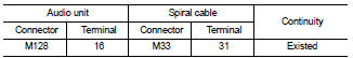
1. Disconnect audio unit connector and spiral cable connector.
2. Check continuity between audio unit harness connector and spiral cable harness connector.
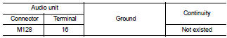
3. Check continuity between audio unit harness connector and ground.
Is the inspection result normal? YES >> GO TO 2.
NO >> Repair harness or connector.
2.CHECK SPIRAL CABLE
Check spiral cable.
Is the inspection result normal? YES >> GO TO 3.
NO >> Replace spiral cable. Refer to SR-16, "Exploded View".
3.CHECK AUDIO UNIT VOLTAGE
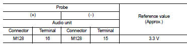
1. Connect audio unit connector and spiral cable connector.
2. Turn ignition switch ON.
3. Check voltage between audio unit harness connector.
Is the inspection result normal? YES >> GO TO 4.
NO >> Replace audio unit. Refer to AV-38, "Removal and Installation".
4.CHECK STEERING SWITCH
1. Turn ignition switch OFF.
2. Check steering switch. Refer to AV-30, "Component Inspection".
Is the inspection result normal? YES >> INSPECTION END
NO >> Replace steering switch. Refer to AV-44, "Exploded View".
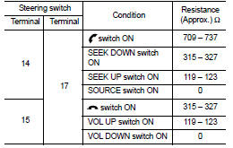
Component Inspection
Measure the resistance between the steering switch connector.
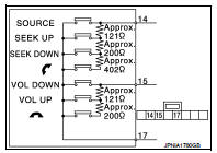
Standard
 Steering switch signal a circuit
Description
Transmits the steering switch signal to audio unit.
Diagnosis Procedure
1.CHECK STEERING SWITCH SIGNAL A CIRCUIT
1. Disconnect audio unit connector and spiral cable connector.
2. Chec ...
 Steering switch ground circuit
Description
Transmits the steering switch signal to audio unit.
Diagnosis Procedure
1.CHECK STEERING SWITCH SIGNAL GROUND CIRCUIT
1. Disconnect audio unit connector and spiral cable connector.
2. ...
Other materials:
B2623 inside antenna
DTC Logic
DTC DETECTION LOGIC
DTC CONFIRMATION PROCEDURE
1.PERFORM DTC CONFIRMATION PROCEDURE
1. Select “INTELLIGENT KEY” of “BCM” using CONSULT-III.
2. Select “INSIDE ANT DIAGNOSIS” in “WORK SUPPORT” mode.
3. Perform inside key antenna (“INSIDE ANT DIAGNOSIS”) on “WORK SUPPORT” of
“INTELLIG ...
P1614 chain of IMMU-KEY
DTC Logic
DTC DETECTION LOGIC
DTC CONFIRMATION PROCEDURE
1.PERFORM DTC CONFIRMATION PROCEDURE
1. Turn ignition switch ON.
2. Check DTC in “Self Diagnostic Result” mode of “ENGINE” using CONSULT-III.
Is DTC detected?
YES >> Refer to SEC-195, "Diagnosis Procedure".
NO > ...
B261A Push-button ignition switch
DTC Logic
DTC DETECTION LOGIC
NOTE:
• If DTC B261A is displayed with DTC U1000, first perform the trouble diagnosis
for DTC U1000. Refer to
BCS-83, "DTC Logic".
• If DTC B261A is displayed with DTC U1010, first perform the trouble diagnosis
for DTC U1010. Refer to
BCS-84, "D ...
