Nissan Juke Service and Repair Manual : Steering switch ground circuit
Description
Transmits the steering switch signal to audio unit.
Diagnosis Procedure
1.CHECK STEERING SWITCH SIGNAL GROUND CIRCUIT
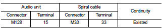
1. Disconnect audio unit connector and spiral cable connector.
2. Check continuity between audio unit harness connector and spiral cable harness connector.
Is the inspection result normal? YES >> GO TO 2.
NO >> Repair harness or connector.
2.CHECK SPIRAL CABLE
Check spiral cable.
Is the inspection result normal? YES >> GO TO 3.
NO >> Replace spiral cable. Refer to SR-16, "Exploded View".
3.CHECK GROUND CIRCUIT
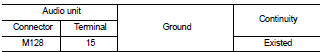
1. Connect audio unit connector.
2. Check continuity between audio unit harness connector and ground.
Is the inspection result normal? YES >> GO TO 4.
NO >> Replace audio unit. Refer to AV-38, "Removal and Installation".
4.CHECK STEERING SWITCH
1. Turn ignition switch OFF.
2. Check steering switch. Refer to AV-31, "Component Inspection".
Is the inspection result normal? YES >> INSPECTION END
NO >> Replace steering switch. Refer to AV-44, "Exploded View".
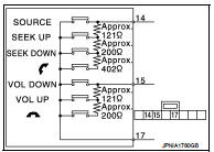
Component Inspection
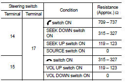
Measure the resistance between the steering switch connector.
Standard
 Steering switch signal B circuit
Description
Transmits the steering switch signal to audio unit.
Diagnosis Procedure
1.CHECK STEERING SWITCH SIGNAL B CIRCUIT
1. Disconnect audio unit connector and spiral cable connector.
2. Chec ...

Other materials:
Basic inspection
DIAGNOSIS AND REPAIR WORKFLOW
Work Flow
OVERALL SEQUENCE
DETAILED FLOW
1.INTERVIEW FOR MALFUNCTION
Interview the symptom to the customer.
>> GO TO 2.
2.SYMPTOM CHECK
Check the symptom from the customer's information.
>> GO TO 3.
3.BASIC INSPECTION
Check the operation o ...
P181E steering angle sensor
DTC Logic
DTC DETECTION LOGIC
DTC CONFIRMATION PROCEDURE
1.PRECONDITIONING
If “DTC CONFIRMATION PROCEDURE” has been previously conducted, always turn
ignition switch OFF and
wait at least 10 seconds before conducting the next test.
>> GO TO 2.
2.DTC REPRODUCTION PROCEDURE
With ...
System
Starting system (with intelligent key) : System Diagram
*1: M/T models
*2: CVT models
Starting system (with intelligent key) : System Description
CVT MODELS
• When selector lever is P or N, power is supplied to starter relay and
starter control relay by transmission
range switch. And BCM a ...
