Nissan Juke Service and Repair Manual : Starter motor drive control
Starter motor drive control : System Diagram
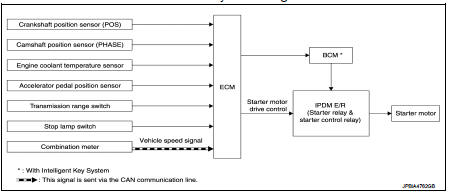
Starter motor drive control : System DescriptionINPUT/OUTPUT SIGNAL CHART
INPUT/OUTPUT SIGNAL CHART
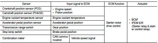
*: With Intelligent Key system SYSTEM DESCRIPTION
When rapid deceleration occurs during engine runs or idle speed decreases due
to heavy load conditions,
ECM detects a decrease in idle speed and restarts the engine to secure
reliability in handleability by transmitting
a cranking request signal to IPDM E/R for activating the starter motor under the
following conditions:
• Selector lever: P or any position other than N
• Idle switch: ON (Accelerator pedal not depressed)
• Brake switch: ON (Brake pedal depressed)
Models with no Intelligent Key System transmit a control signal directly to IPDM E/R. On the other hand, models with the Intelligent Key System transmit a control signal to IPDM E/R by way of BCM via CAN communication.
IPDM E/R detects an operating state of the starter motor relay and the starter motor control relay and transmits a feed back signal to ECM via CAN Communication.
 Cooling fan control
Cooling fan control : System Diagram
Cooling fan control : System Description
INPUT/OUTPUT SIGNAL CHART
*: The ECM determines the start signal status by the signals of engine speed
and batter ...
 Evaporative emission system
Evaporative emission system: System
Diagram
Evaporative emission system : System
Description
INPUT/OUTPUT SIGNAL CHART
*: ECM determines the start signal status by the signals of engine spee ...
Other materials:
Headlamp washer circuit
Component Function Check
1.CHECK HEADLAMP WASHER OPERATION
CONSULT-III ACTIVE TEST
1. Select “HEAD LAMP WASHER” of IPDM E/R active test item.
2. With operating the test item, check headlamp operation.
On :Headlamp washer ON operation
Off :Stop the headlamp washer.
Is headlamp washer operation ...
Front drive shaft boot
Exploded View
LEFT SIDE
1. Circular clip
2. Dust shield
3. Housing assembly
4. Boot band
5. Boot
6. Damper band
7. Dynamic damper
8. Circular clip
9. Joint sub-assembly
: Wheel side
: Fill NISSAN Genuine grease or
equivalent.
: Always replace after every
disassembly.
RIGHT ...
A/C auto AMP. Connection recognition signal circuit
Diagnosis Procedure
1.CHECK A/C AUTO AMP. CONNECTION RECOGNITION SIGNAL
1. Turn ignition switch ON.
2. Check voltage between combination meter harness connector and ground.
Is the inspection result normal?
YES >> INSPECTION END
NO >> GO TO 2.
2.CHECK A/C AUTO AMP. CONNECTION R ...
