Nissan Juke Service and Repair Manual : Sectional View
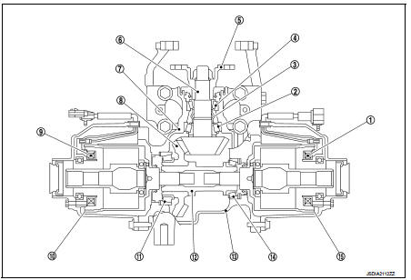
1. 4WD solenoid (RH)
2. Pinion rear bearing
3. Collapsible spacer
4. Pinion front bearing
5. Companion flange
6. Drive pinion
7. Gear carrier
8. Drive gear
9. 4WD solenoid (LH)
10. Electric controlled coupling (LH)
11. Side bearing (LH)
12. Center stem
13. Rear cover
14. Side bearing (RH)
15. Electric controlled coupling (RH)
 System description
STRUCTURE AND OPERATION ...
 Electric controlled coupling
The electric controlled coupling operates as the 4WD system. For the
operation, refer to DLN-15, "Operation
Principle". ...
Other materials:
Shift position indicator circuit
Description
• TCM sends position indicator signals to combination meter by CAN
communication line.
• Manual mode switch position is indicated on shift position indicator
Component Function Check
1.CHECK SHIFT POSITION INDICATOR
CAUTION:
Always drive vehicle at a safe speed.
1. Start engine. ...
B1122, B1123, B1124, B1125, B1126, B1127 diagnosis sensor unit
DTC Logic
DTC DETECTION LOGIC
DTC CONFIRMATION PROCEDURE
1.CHECK SELF-DIAG RESULT
With CONSULT-III
1. Turn ignition switch ON.
2. Perform “Self Diagnostic Result” mode of “AIR BAG” using CONSULT-III.
Without CONSULT-III
1. Turn ignition switch ON.
2. Check the air bag warning lamp statu ...
B1212, B1213, B1214 satellite sensor RH
DTC Logic
DTC DETECTION LOGIC
DTC CONFIRMATION PROCEDURE
1.CHECK SELF-DIAG RESULT
With CONSULT-III
1. Turn ignition switch ON.
2. Perform “Self Diagnostic Result” mode of “AIR BAG” using CONSULT-III.
Without CONSULT-III
1. Turn ignition switch ON.
2. Check the air bag warning lamp statu ...
