Nissan Juke Service and Repair Manual : Rocker cover
Exploded View
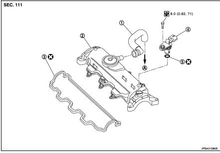
1. Blow-by hose
2. Rocker cover
3. Gasket
4. Camshaft position sensor
5. O-ring
A. To turbocharger air inlet pipe
 : N·m (kg-m, in-lb)
 : Always replace after every
disassembly.
Removal and Installation
REMOVAL
1. Remove air cleaner case. Refer to EM-280, "Exploded View".
2. Remove inlet pipe assembly and air inlet tube. Refer to EM-281, "Exploded View".
3. Remove high pressure protection cover (upper). Refer to EM-294, "Exploded View".
4. Remove electric throttle control actuator.
5. Remove fuel injector. Refer to EM-294, "Exploded View".
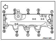
6. Remove rocker cover.
• Loosen holding bolts in the reverse order as shown in the figure and remove.
 : Engine front
INSTALLATION
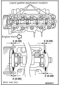
1. Apply liquid gasket on locations shown in the figure.
• Use Genuine Liquid gasket or equivalent.
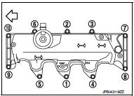
2. Tighten holding bolts in the numerical order as shown in the figure.
: Engine front
 : 12 N·m (1.2 kg-m, 9 ft-lb)
3. Install in the reverse order of removal after this steps.
 High pressure supply pump
Exploded View
1. High pressure supply pump protector
2. High pressure supply pump
: N·m (kg-m, ft-lb)
Removal and Installation
REMOVAL
CAUTION:
• Be sure to read “Precautions for Diesel Equi ...
 Timing belt
Exploded View
1. Timing belt inner cover
2. Timing belt
3. Camshaft sprocket
4. Timing belt tensioner
5. Timing belt upper cover
6. Timing belt lower cover
7. Cylinder head suspended brac ...
Other materials:
P0087, P0088, P0090 FRP control system
DTC Logic
DTC DETECTION LOGIC
NOTE:
• If DTC P0087 or P0090 is displayed with DTC P1197, first perform the trouble
diagnosis for DTC
P1197.
• DTC P0087 or P0090 may be displayed when running out of gas.
DTC CONFIRMATION PROCEDURE
1.PRECONDITIONING
If DTC Confirmation Procedure has been p ...
Rear drive shaft
Exploded View
1. Circular clip
2. Dust shield
3. Housing
4. Snap ring
5. Ball cage/steel ball/inner race assembly
6. Stopper ring
7. Boot band
8. Boot
9. Shaft
10. Joint sub-assembly
11. Sensor rotor
: Wheel side
: Fill NISSAN genuine grease or an
equivalent.
: Always replace ...
Wiring diagram
METER SYSTEM
Wiring Diagram
For connector terminal arrangements, harness layouts, and alphabets in a
(option abbreviation; if not
described in wiring diagram), refer to GI-12, "Connector Information/Explanation
of Option Abbreviation".
...
