Nissan Juke Service and Repair Manual : Remote keyless entry receiver
Component Function Check
1.CHECK FUNCTION
1. Select “INTELLIGENT KEY” of “BCM” using CONSULT-III.
2. Select “RKE OPE COUN1” in “DATA MONITOR” mode.
3. Check that the function operates normally according to the following conditions.

Is the inspection result normal? YES >> Remote keyless entry receiver is OK.
NO >> Refer to DLK-266, "Diagnosis Procedure".
Diagnosis Procedure
1.CHECK REMOTE KEYLESS ENTRY RECEIVER GROUND CIRCUIT
1. Turn ignition switch OFF.
2. Disconnect BCM connector and remote keyless entry receiver connector.
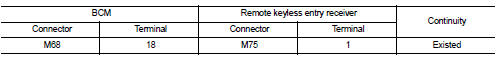
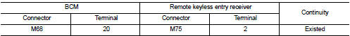
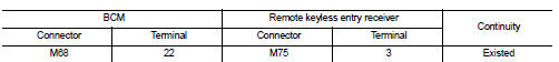
3. Check continuity between BCM harness connector and remote keyless entry receiver harness connector.
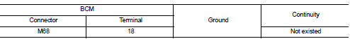
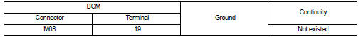
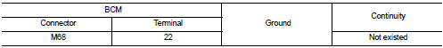
4. Check continuity between BCM harness connector and ground.
Is the inspection result normal? YES >> GO TO 2.
NO >> Repair or replace harness.
2.CHECK REMOTE KEYLESS ENTRY RECEIVER POWER SUPPLY
1. Reconnect BCM connector.
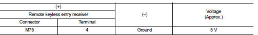
2. Check voltage between remote keyless entry receiver harness connector and ground.
Is the inspection result normal? YES >> GO TO 4.
NO >> GO TO 3.
3.CHECK REMOTE KEYLESS ENTRY RECEIVER CIRCUIT 1
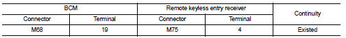
1. Disconnect BCM connector 2. Check continuity between BCM harness connector and remote keyless entry receiver harness connector.
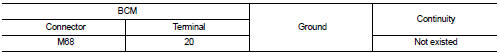
3. Check continuity between BCM harness connector and ground.
Is the inspection result normal? YES >> Replace BCM. Refer to BCS-93, "Removal and Installation".
NO >> Repair or replace harness.
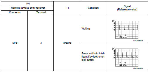
4.CHECK REMOTE KEYLESS ENTRY RECEIVER OUTPUT SIGNAL
1. Reconnect remote keyless entry receiver connector.
2. Check signal between remote keyless entry receiver harness connector and ground using oscilloscope.
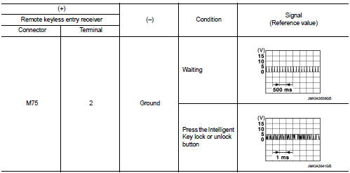
Is the inspection result normal? YES >> GO TO 5.
NO >> Replace remote keyless entry receiver.
5.CHECK REMOTE KEYLESS ENTRY RECEIVER CIRCUIT 2
1. Disconnect BCM connector and remote keyless entry receiver connector.
2. Check continuity between BCM harness connector and remote keyless entry receiver harness connector.
3. Check continuity between BCM harness connector and ground.
Is the inspection result normal? YES >> GO TO 6.
NO >> Repair or replace harness.
6.CHECK REMOTE KEYLESS ENTRY RECEIVER RSSI OUTPUT SIGNAL
1. Reconnect BCM and remote keyless entry receiver connector.
2. Check signal between remote keyless entry receiver harness connector and ground using oscilloscope.
Is the inspection result normal? YES >> GO TO 7.
NO >> Replace remote keyless entry receiver.
7.CHECK REMOTE KEYLESS ENTRY RECEIVER RSSI CIRCUIT
1. Disconnect BCM and remote keyless entry receiver connector.
2. Check continuity between BCM harness connector and remote keyless entry receiver harness connector.
3. Check continuity between BCM harness connector and ground.
Is the inspection result normal? YES >> Replace BCM. Refer to BCS-93, "Removal and Installation".
NO >> Repair or replace harness.
 Key warning lamp
Component Function Check
1.CHECK FUNCTION
1. Select “INTELLIGENT KEY” of “BCM” using CONSULT-III.
2. Select “INDICATOR” in “ACTIVE TEST” mode.
3. Check that the function operates normally accordin ...
 Shift P warning lamp
Component Function Check
1.CHECK FUNCTION
1. Select “INTELLIGENT KEY” of “BCM” using CONSULT-III.
2. Select “LCD” in “ACTIVE TEST” mode.
3. Check that the function operates normally according to t ...
Other materials:
P0139 HO2S2
DTC Logic
DTC DETECTION LOGIC
The heated oxygen sensor 2 has a much longer switching time
between rich and lean than the air fuel ratio (A/F) sensor 1. The oxygen
storage capacity of the three way catalyst (manifold) causes the
longer switching time. To judge the malfunctions of heated oxygen
...
Back door opener system
System Diagram
System Descr
BACK DOOR OPENER OPERATION
When back door opener switch is pressed, BCM operates back door opener
actuator.
NOTE:
Back door opener actuator is not for locking the back door. The function is only
to open the back door.
OPERATION CONDITION
If the following ...
Cooling fan
Exploded View
1. Fan motor
2. Fan shroud
3. Cooling fan
A. Apply on fan motor shaft
: N·m (kg-m, in-lb)
: Apply genuine high strength thread
locking sealant or equivalent.
Removal and Installation
REMOVAL
1. Drain engine coolant. Refer to CO-11, "Draining".
CAUTION:
• Pe ...
