Nissan Juke Service and Repair Manual : Remote keyless entry receiver
Component Function Check
1.CHECK FUNCTION
1. Select “INTELLIGENT KEY” of “BCM” using CONSULT-III.
2. Select “RKE OPE COUN1” in “DATA MONITOR” mode.
3. Check that the function operates normally according to the following conditions.

Is the inspection result normal? YES >> Remote keyless entry receiver is OK.
NO >> Refer to DLK-95, "Diagnosis Procedure".
Diagnosis Procedure
1.CHECK REMOTE KEYLESS ENTRY RECEIVER GROUND CIRCUIT
1. Turn ignition switch OFF.
2. Disconnect BCM connector and remote keyless entry receiver connector.
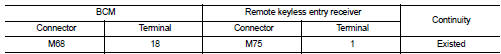
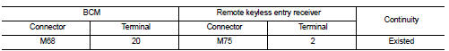
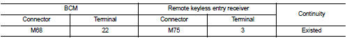
3. Check continuity between BCM harness connector and remote keyless entry receiver harness connector.
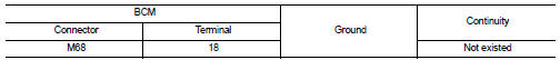
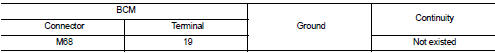
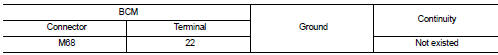
4. Check continuity between BCM harness connector and ground.
Is the inspection result normal? YES >> GO TO 2.
NO >> Repair or replace harness.
2.CHECK REMOTE KEYLESS ENTRY RECEIVER POWER SUPPLY
1. Reconnect BCM connector.
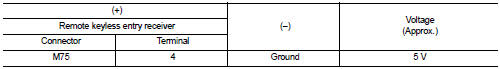
2. Check voltage between remote keyless entry receiver harness connector and ground.
Is the inspection result normal? YES >> GO TO 4.
NO >> GO TO 3.
3.CHECK REMOTE KEYLESS ENTRY RECEIVER CIRCUIT 1
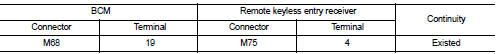
1. Disconnect BCM connector 2. Check continuity between BCM harness connector and remote keyless entry receiver harness connector.
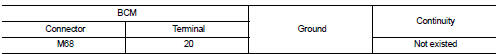
3. Check continuity between BCM harness connector and ground.
Is the inspection result normal? YES >> Replace BCM. Refer to BCS-93, "Removal and Installation".
NO >> Repair or replace harness.
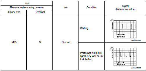
4.CHECK REMOTE KEYLESS ENTRY RECEIVER OUTPUT SIGNAL
1. Reconnect remote keyless entry receiver connector.
2. Check signal between remote keyless entry receiver harness connector and ground using oscilloscope.
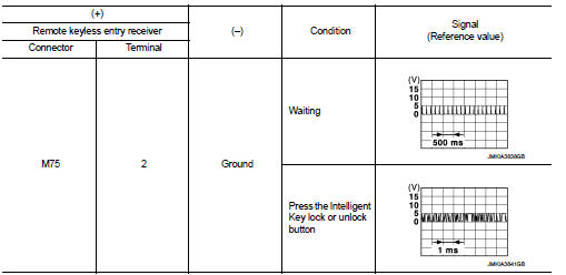
Is the inspection result normal? YES >> GO TO 5.
NO >> Replace remote keyless entry receiver.
5.CHECK REMOTE KEYLESS ENTRY RECEIVER CIRCUIT 2
1. Disconnect BCM connector and remote keyless entry receiver connector.
2. Check continuity between BCM harness connector and remote keyless entry receiver harness connector.
3. Check continuity between BCM harness connector and ground.
Is the inspection result normal? YES >> GO TO 6.
NO >> Repair or replace harness.
6.CHECK REMOTE KEYLESS ENTRY RECEIVER RSSI OUTPUT SIGNAL
1. Reconnect BCM and remote keyless entry receiver connector.
2. Check signal between remote keyless entry receiver harness connector and ground using oscilloscope.
Is the inspection result normal? YES >> GO TO 7.
NO >> Replace remote keyless entry receiver.
7.CHECK REMOTE KEYLESS ENTRY RECEIVER RSSI CIRCUIT
1. Disconnect BCM and remote keyless entry receiver connector.
2. Check continuity between BCM harness connector and remote keyless entry receiver harness connector.
3. Check continuity between BCM harness connector and ground.
Is the inspection result normal? YES >> Replace BCM. Refer to BCS-93, "Removal and Installation".
NO >> Repair or replace harness.
 Key warning lamp
Component Function Check
1.CHECK FUNCTION
1. Select “INTELLIGENT KEY” of “BCM” using CONSULT-III.
2. Select “INDICATOR” in “ACTIVE TEST” mode.
3. Check that the function operates normally accordin ...
 Shift P warning lamp
Component Function Check
1.CHECK FUNCTION
1. Select “INTELLIGENT KEY” of “BCM” using CONSULT-III.
2. Select “LCD” in “ACTIVE TEST” mode.
3. Check that the function operates normally according to t ...
Other materials:
Check anti-pinch function
Description
If any of the following operations are performed, the initialization is
necessary for normal operation of antipinch
function.
• Disconnection and connection of battery cable from negative terminal.
• When power window main switch replaced.
• Electric power supply to power window ...
Auto door lock operation does not operate
Diagnosis Procedure
1.CHECK “AUTO LOCK SET” SETTING IN “WORK SUPPORT”
1. Select “INTELLIGENT KEY” of “BCM” using CONSULT-III.
2. Select “AUTO LOCK SET” in “WORK SUPPORT” mode.
3. Check “AUTO LOCK SET” in “WORK SUPPORT”.
Refer to DLK-219, "INTELLIGENT KEY : CONSULT-III Function (BCM - INT ...
B260B steering lock unit
DTC Logic
DTC DETECTION LOGIC
DTC CONFIRMATION PROCEDURE
1.PERFORM DTC CONFIRMATION PROCEDURE
1. Turn ignition switch ON.
2. Turn ignition switch OFF.
3. Press driver side door switch.
4. Shift selector lever to the P position.
5. Press push-button ignition switch under the following condi ...
