Nissan Juke Service and Repair Manual : Rear wiper auto stop signal circuit
Component Function Check
1.CHECK REAR WIPER (AUTO STOP) OPERATION
 CONSULT-III DATA MONITOR
1. Select “WIPER” of BCM data monitor item.
2. Operate the rear wiper.
3. Check that “RR WIPER STOP” changes to “On” and “Off” linked with the wiper operation.
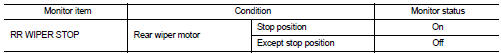
Is the status of item normal? YES >> Rear wiper auto stop signal circuit is normal.
NO >> Refer to WW-47, "Diagnosis Procedure".
Diagnosis Procedure
1.CHECK REAR WIPER MOTOR (AUTO STOP) OUTPUT VOLTAGE
1. Turn ignition switch OFF.
2. Disconnect rear wiper motor connector.
3. Turn ignition switch ON.
4. Check voltage between rear wiper motor harness connector and ground.
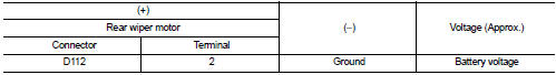
Is the inspection result normal? YES >> Replace rear wiper motor.
NO >> GO TO 2.
2.CHECK REAR WIPER MOTOR (AUTO STOP) CIRCUIT
1. Turn ignition switch OFF.
2. Disconnect BCM connector.
3. Check continuity between BCM harness connector and rear wiper motor harness connector.
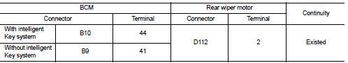
4. Check continuity between BCM harness connector and ground.
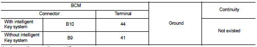
Is the inspection result normal?
YES >> Replace BCM. Refer to BCS-93, "Removal and Installation".
NO >> Repair or replace harness.
 Rear wiper motor circuit
Component Function Check
1.CHECK REAR WIPER ON OPERATION
CONSULT-III ACTIVE TEST
1. Select “RR WIPER” of BCM active test item.
2. With operating the test item, check rear wiper operation.
On : Re ...
 Headlamp washer relay
Component Inspection
1.CHECK HEADLAMP WASHER RELAY
1. Turn the ignition switch OFF.
2. Remove headlamp washer relay.
3. Apply battery voltage to headlamp washer relay between terminals 1 and 2.
4 ...
Other materials:
Rear disc brake
Brake pad : Exploded View
1. Sliding pin bolt
2. Cylinder body
3. Inner shim cover
4. Inner shim
5. Inner pad (with pad wear sensor)
6. Pad retainer
7. Torque member
8. Outer pad
9. Outer shim
10. Outer shim cover
1 Apply rubber grease.
2: Apply MOLYKOTE® AS880N or
silicone-bas ...
Removal and Installation Procedure for CVT Unit Connector
REMOVAL
• Rotate bayonet ring (A) counterclockwise. Pull out CVT unit harness
connector (B) upward and remove it.
INSTALLATION
1. Align marking (A) on CVT unit harness connector terminal with
marking (B) on bayonet ring. Insert CVT unit harness connector.
2. Rotate bayonet ring clockwise.
...
Automatic air conditioner (with Integrated Control System)
1. AUTO button/Temperature control dial
2. OFF button
3. A/C button
4. CLIMATE button
5. Display screen
6. Air flow control buttons
7. Fan speed control dial
8. Front defroster button
9. Air intake button (Outside air circulation
/Air recirculation
)
10. Rear window defroster button ( ...
