Nissan Juke Service and Repair Manual : Rear suspension beam
Exploded View
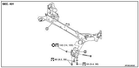
1. Rear suspension beam 2. Rear suspension arm bracket
 : Always replace after every
disassembly.
 : N·m (kg-m, ft-lb)
Removal and Installation
REMOVAL
1. Remove tires. Refer to WT-7, "Removal and Installation".
2. Drain brake fluid. Refer to BR-12, "Draining" (LHD), BR-80, "Draining" (RHD).
3. Remove wheel sensor and sensor harness. Refer to BRC-86, "REAR WHEEL SENSOR : Removal and Installation" (Without ESP), BRC-227, "REAR WHEEL SENSOR : Removal and Installation" (With ESP).
4. Remove brake caliper assembly. Refer to BR-65, "BRAKE CALIPER ASSEMBLY : Removal and Installation" (LHD), BR-131, "BRAKE CALIPER ASSEMBLY : Removal and Installation" (RHD).
5. Remove disc rotor. Refer to RAX-5, "Removal and Installation".
6. Remove parking brake cable from back plate and rear suspension beam. Refer to PB-5, "Removal and Installation".
7. Set suitable jack under rear suspension beam.
CAUTION:
• Never damage the suspension beam with a jack.
• Check the stable condition when using a jack.
8. Remove shock absorber mounting bolts (lower side). Refer to RSU-8, "Removal and Installation".
9. Remove coil spring. Refer to RSU-11, "Removal and Installation".
10. Separate brake hose and brake tube. Refer to BR-35, "REAR : Removal and Installation" (LHD), BR-101, "REAR : Removal and Installation" (RHD).
11. Remove rear suspension arm bracket mounting bolts.
12. Slowly lower jack, remove rear suspension arm bracket and rear suspension beam from vehicle.
CAUTION:
Operate while checking that jack supporting status is stable.
13. Remove wheel hub assembly. Refer to RAX-5, "Removal and Installation".
14. Remove parking brake shoe assembly. Refer toPB-7, "Removal and Installation".
15. Remove rear suspension arm bracket from rear suspension beam.
16. Perform inspection after removal. Refer to RSU-14, "Inspection".
INSTALLATION
Note the following, and install in the reverse order of removal.
• Never reuse rear suspension beam mounting nut.
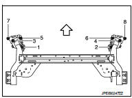
• To install rear suspension arm bracket to the vehicle, temporarily tighten the bolts before tightening to the specified torque, referring to the tightening method and the numerical order shown below:
Temporary tightening : 1 → 2 → 3 → 4 Final tightening (specified torque) : 5 → 6 → 7 → 8 → 9 → 10 → 11 → 12
 : Vehicle front
• Perform final tightening of rear suspension beam installation position (rubber bushing), under unladen conditions with tires on level ground.
• Perform inspection after installation. Refer to RSU-14, "Inspection".
Inspection
INSPECTION AFTER REMOVAL
Check rear suspension beam and rear suspension beam bracket for deformation, cracks or damage. Replace the part if necessary.
INSPECTION AFTER INSTALLATION
1. Check wheel sensor harness for proper connection. Refer toBRC-85, "REAR WHEEL SENSOR : Exploded View" (Without ESP), BRC-225, "REAR WHEEL SENSOR : Exploded View" (With ESP).
2. Adjust parking brake. Refer to PB-2, "Inspection and Adjustment".
3. Check wheel alignment. Refer to RSU-6, "Inspection".
4. Adjust neutral position of steering angle sensor. Refer to BRC-149, "Work Procedure". (With ESP)
 Coil spring
Exploded View
1. Upper rubber seat
2. Coil spring
3. Lower rubber seat
4. Rear suspension beam
Removal and Installation
REMOVAL
1. Remove tires. Refer to WT-7, "Removal and Installatio ...

Other materials:
U1000 can comm
Description
CAN (Controller Area Network) is a serial communication line for real time
applications. It is an on-vehicle multiplex
communication line with high data communication speed and excellent error
detection ability. Modern
vehicle is equipped with many electronic control unit, and eac ...
B2603 shift position
DTC Logic
DTC DETECTION LOGIC
NOTE:
• If DTC B2603 is displayed with DTC B2601, first perform the trouble diagnosis
for DTC B2601. Refer to
SEC-79, "DTC Logic".
DTC CONFIRMATION PROCEDURE
1.PERFORM DTC CONFIRMATION PROCEDURE 1
1. Shift the selector lever to the P position.
2. T ...
P0705 transmission range switch A
DTC Logic
DTC DETECTION LOGIC
DTC CONFIRMATION PROCEDURE
CAUTION:
Be careful of the driving speed.
1.PREPARATION BEFORE WORK
If another "DTC CONFIRMATION PROCEDURE" occurs just before, turn ignition
switch OFF and wait for at
least 10 seconds, then perform the next test.
> ...
