Nissan Juke Service and Repair Manual : Rear seat (4WD)
Exploded View
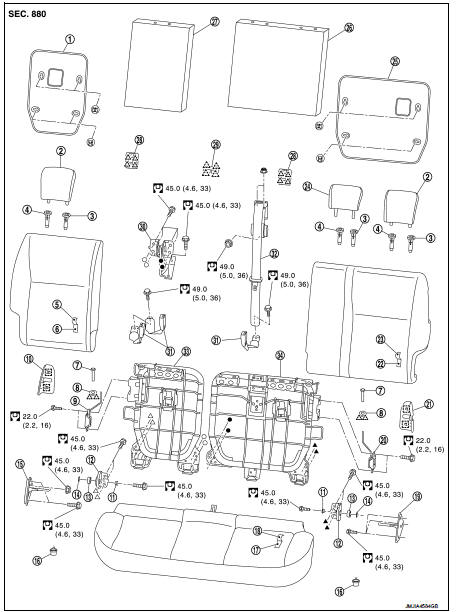
1. Seatback board RH
2. Headrest
3. Headrest holder (locked)
4. Headrest holder (free)
5. Seatback trim RH
6. Seatback pad RH
7. Seatback lock knob
8. Seatback lock knob finisher
9. Seatback lock assembly RH
10. Seat lock cover RH
11. Bush
12. Side hinge
13. Spacer
14. Lock washer
15. Striker RH
16. Seat cushion hook
17. Seat cushion pad
18. Seat cushion trim
19. Striker LH
20. Seatback lock assembly LH
21. Seat lock cover LH
22. Seatback pad LH
23. Seatback trim LH
24. Center headrest
25. Seatback board LH
26. Seatback silencer LH
27. Seatback silencer RH
28. Seatback tether cover
29. Center seat belt finisher
30. Center hinge
31. Seat belt buckle
32. Center seat belt
33. Seatback frame RH
34. Seatback frame LH
 : Pawl
 : Metal clip
 : N·m (kg-m, ft-lb)
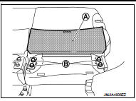
Seat cushion : Removal and Installation
REMOVAL
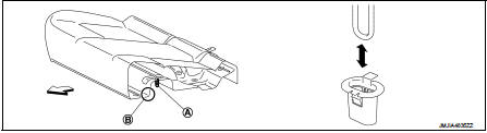
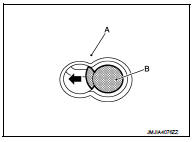
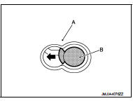
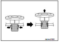
1. Lift up seat cushion at a close position (B) of engaging portion (A) and disengage seat cushion hook.
 : Vehicle front
CAUTION:
Seat cushion wire close to engaging portion deforms, if excessive force is
applied to seat cushion
front end when removing seat cushion.
To avoid the deformation, be careful to remove seat cushion while applying force to close position, as much as possible, of engaging portion.
2. Pull out seat belt buckle from seat cushion.
3. Remove seat cushion from the vehicle.
CAUTION:
When removing and installing, use shop cloths to protect parts from damage.
INSTALLATION
Note the following item, and install in the reverse order of removal.
CAUTION:
When removing and installing, use shop cloths to protect parts from damage.
Seat cushion : Disassembly and Assembly
DISASSEMBLY
Remove hog rings, and separate the seat cushion trim and seat cushion pad.
CAUTION:
Before performing separating operation, check the installation position of hog
rings.
ASSEMBLY
Note the following item, and assemble in the reverse order of disassembly.
CAUTION:
Always install the hog ring in position.
Seatback : Removal and Installation
LH SIDE SEATBACK
Removal
CAUTION:
Remove seatback with seat cushion installed.
1. Temporarily move seat cushion to the position where center anchor of center seat belts can be removed.
2. Remove center anchor mounting bolt of center seat belt. Remove center anchor.
3. Return seat cushion to the normal position.
4. Unlock seatback lock assembly. Tilt seatback toward vehicle front. Remove headrests.
5. Fold seatback toward vehicle front.
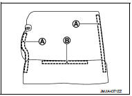
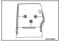
6. Pull up seatback carpet (A). Remove mounting bolts (B) of seatback hinge portion.
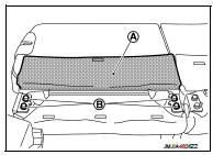
7. Remove seatback from the vehicle.
CAUTION:
When removing and installing, use shop cloths to protect parts from damage.
Installation
Note the following items, and install in the reverse order of removal.
CAUTION:
• When removing and installing, use shop cloths to protect parts from damage.
• Install seat cushion to the vehicle, and then install seatback.
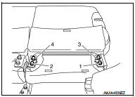
• Temporarily tighten bolts, fold up seatback, check that lock and striker do not interfere, and then tighten bolts.
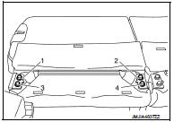
• When installing seatback, tighten mounting bolts according to the numerical order (1, 2, 3, and 4 as shown in the figure).
RH SIDE SEATBACK
Removal
CAUTION:
Remove seatback with seat cushion installed.
1. Unlock seatback lock assembly. Tilt seatback toward vehicle front. Remove headrests.
2. Fold seatback toward vehicle front.
3. Pull up seatback carpet (A). Remove mounting bolts (B) of seatback hinge portion.
4. Remove seatback from the vehicle.
CAUTION:
When removing and installing, use shop cloths to protect parts from damage.
Installation
Note the following items, and install in the reverse order of removal.
CAUTION:
• When removing and installing, use shop cloths to protect parts from damage.
• Install seat cushion to the vehicle, and then install seatback.
• Temporarily tighten bolts, fold up seatback, check that lock and striker do not interfere, and then tighten bolts.
• When installing seatback, tighten mounting bolts according to the numerical order (1, 2, 3, and 4 as shown in the figure).
Seatback : Disassembly and Assembly
DISASSEMBLY
LH side seatback
1. Remove headrest holder.
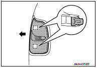
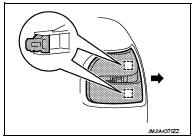
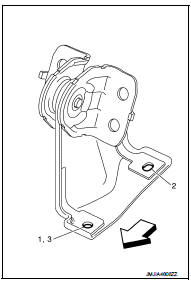
1. Pull seat lock cover in direction indicated by the arrow as shown in the figure. Remove seat lock cover.
 : Metal clip
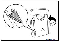
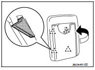
2. Pull tether cover in direction indicated by the arrow as shown in the figure. Remove tether cover.
 : Pawl
3. Open seatback fastener (A) and remove seatback retainer (B).
4. Slide and align the clips (B) to the holes on the seatback as shown in the figure, and then remove the seatback board (A).
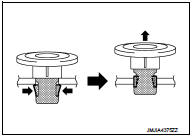
5. Use pincers, etc., to press up pawls as shown by the arrows in the figure, and remove headrest holder from seatback.
CAUTION:
Before installing headrest holder check its orientation.
(front/rear and right/left)
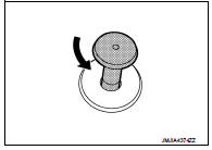
2. Remove seatback lock knob finisher.
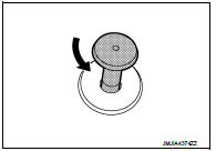
1. Rotate seatback lock knob counterclockwise. Remove seatback lock knob.
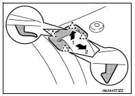
2. Push up seatback lock knob finisher while pressing pawls indicated by arrows as shown in the figure. Remove seatback lock finisher from seatback.
CAUTION:
When installing seatback lock knob finisher, check
front and rear orientation and be careful to install it normally.
3. Remove center seat belt finisher from seatback.
Lift up front of center seat belt finisher. Disengage front pawls.
Pull center seat belt finisher toward seat front. Disengage rear pawls.
 : Pawl
4. Remove seatback trim and seatback pad from seatback frame 5. Remove hog rings, and separate the seatback trim and seatback pad.
CAUTION:
Before performing separating operation, check the installation position of hog
rings.
6. Remove seatback silencer from seatback frame.
7. Remove seatback lock assembly mounting bolts, and then remove seatback lock assembly from seatback frame.
8. Remove center seat belt retractor from seatback frame.
Refer to SB-12, "SEAT BELT RETRACTOR : Removal and Installation".
RH side seatback
1. Remove headrest holder.
1. Pull seat lock cover in direction indicated by the arrow as shown in the figure. Remove seat lock cover.
 : Metal clip
2. Pull tether cover in direction indicated by the arrow as shown in the figure. Remove tether cover.
 : Pawl
3. Open seatback fastener (A) and remove seatback retainer (B).
4. Slide and align the clips (B) to the holes on the seatback as shown in the figure, and then remove the seatback board (A).
5. Use pincers, etc., to press up pawls as shown by the arrows in the figure, and remove headrest holder from seatback.
CAUTION:
Before installing headrest holder check its orientation.
(front/rear and right/left)
2. Remove seatback lock knob finisher.
1. Rotate seatback lock knob counterclockwise. Remove seatback lock knob.
2. Push up seatback lock knob finisher while pressing pawls indicated by arrows as shown in the figure. Remove seatback lock finisher from seatback.
CAUTION:
When installing seatback lock knob finisher, check
front and rear orientation and be careful to install it normally.
3. Remove seatback trim and seatback pad from seatback frame.
4. Remove hog rings, and separate the seatback trim and seatback pad.
CAUTION:
Before performing separating operation, check the installation position of hog
rings.
5. Remove seatback silencer from seatback frame.
6. Remove seatback lock assembly mounting bolts, and then remove seatback lock assembly from seatback frame.
INSTALLATION
Note the following, and assemble in the reverse order of disassembly.
CAUTION:
Always install the hog ring in position.
Seatback hinge : Removal and Installation
CENTER HINGE
Removal
1. Remove seatback LH and RH from the vehicle.
Refer to SE-43, "SEATBACK : Removal and Installation".
2. Remove seat cushion from the vehicle.
Refer to SE-42, "SEAT CUSHION : Removal and Installation".
3. Remove center hinge mounting bolts, and then remove center hinge from the vehicle.
Installation
Note the following items, and install in the reverse order of removal.
CAUTION:
When installing center hinge, tighten mounting bolts to the specified torque
according to the numerical
order as shown in the figure
1. Temporarily tighten mounting bolt (1).
2. Tighten mounting bolts in numerical order (2 and 3 as shown in the figure) to the specified torque.
For the specified torque, refer to SE-41, "Exploded View".
 : Vehicle front
SIDE HINGE
Removal
1. Remove seatback from the vehicle.
Refer to SE-43, "SEATBACK : Removal and Installation".
2. Remove side hinge mounting bolt, and then remove side hinge from luggage side lower finisher.
Installation
Installation is the reverse order of removal. Tighten bolts to the specified
torque.
For the specified torque, refer to SE-41, "Exploded View".
Seatback striker : Removal and Installation
REMOVAL
1. Remove seatback LH and RH from the vehicle.
Refer to SE-43, "SEATBACK : Removal and Installation".
2. Remove seat cushion from the vehicle.
Refer to SE-42, "SEAT CUSHION : Removal and Installation".
3. Remove side hinge from the vehicle.
Refer to SE-48, "SEATBACK HINGE : Removal and Installation".
4. Remove luggage side lower finisher from the vehicle.
Refer to INT-31, "LUGGAGE SIDE LOWER FINISHER : Removal and Installation".
5. Remove outer anchor mounting anchor bolt, and then remove outer anchor.
6. Remove mounting bolts or nuts of striker, and then remove striker from the vehicle.
INSTALLATION
Note the following items, and install in the reverse order of removal.
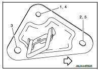
CAUTION:
When installing striker, tighten mounting bolts or nuts to the specified torque
according to the numerical
order as shown in the figure.
1. Temporarily tighten mounting bolts in numerical order (1 and 2 as shown in the figure).
2. Tighten mounting bolts or nuts to the specified torque in numerical order (3, 4, and 5 as shown in the figure).
For the specified torque, refer to SE-41, "Exploded View".
 : Vehicle front
 Rear seat (2WD)
Exploded View
1. Headrest
2. Headrest holder (locked)
3. Headrest holder (free)
4. Seatback trim RH
5. Seatback pad RH
6. Seat lock cover RH
7. Seatback lock knob
8. Seatback lock knob ...
 Heated seat switch
Exploded View
1. Heated seat swich
2. Switch bracket
3. Console switch finisher
Removal and Installation
REMOVAL
CAUTION:
When removing and installing, use shop cloths to protect from damag ...
Other materials:
Control linkage
Exploded View
1. Bracket
2. Selector cable
3. Shifter lever A
4. Selector lever
5. Cable mounting bracket
6. Tapping bolt
7. Shifter cable
8. Grommet
9. M/T shift selector assembly
10. Shifter lever
11. Shifter lever knob
: Always replace after every
disassembly.
: N·m (kg-m, ...
Power supply and ground circuit
Combination meter
COMBINATION METER : Diagnosis Procedure
1.CHECK FUSE
Check for blown fuses.
Is the inspection result normal?
YES >> GO TO 2.
NO >> Be sure to eliminate cause of malfunction before installing new fuse.
2.CHECK POWER SUPPLY CIRCUIT
Check voltage between comb ...
B257B, B257C ambient sensor
DTC Logic
DTC DETECTION LOGIC
NOTE:
• If DTC is displayed along with DTC U1000, first perform the trouble diagnosis
for DTC U1000. Refer to HAC-
51, "DTC Logic".
• If DTC is displayed along with DTC U1010, first perform the trouble diagnosis
for DTC U1010. HAC-52,
"DTC Logic ...
