Nissan Juke Service and Repair Manual : Rear door
Exploded View
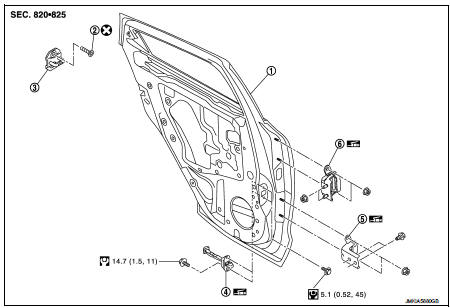
1. Rear door panel
2. TORX bolt
3. Door striker
4. Door check link
5. Door hinge (lower)
6. Door hinge (upper)
 : Do not reuse
 : N·m (kg-m, in-lb)
 : N·m (kg-m, ft-lb)
 : Body grease
Door assembly
DOOR ASSEMBLY : Removal and Installation
CAUTION:
• Perform work with 2 workers, because of it’s heavy weight.
• When removing and installing rear door assembly, support door with a jack and shop cloth to protect door and body.
REMOVAL
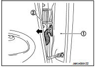
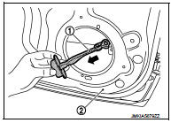
1. Remove rear door harness grommet (2) from body side outer (1), and then pull out rear door harness.
2. Disconnect rear door harness connector.
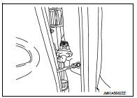
3. Remove mounting bolt of door check link on the vehicle.
4. Remove door hinge mounting bolts (door side), and then remove rear door assembly.
INSTALLATION
Note the following items, and install in the reverse order of removal.
CAUTION:
• Apply anticorrosive agent onto the mounting surface.
• Check rear door open/close, lock/unlock operation after installation.
• Check door hinge rotating part for poor lubrication. If necessary, apply body grease.
• After installation, perform the fitting adjustment. Refer to DLK-575, "DOOR ASSEMBLY : Adjustment".
• After installation, apply touch-up paint (the body color) onto the head of door hinge mounting nuts.
DOOR ASSEMBLY : Adjustment
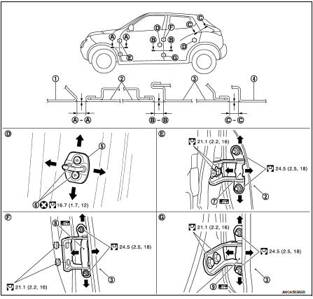
1. Front fender
2. Front door
3. Rear door
4. Body side outer
5. Door striker
6. TORX bolt
7. Front door hinge
8. Rear door hinge (upper)
9. Rear door hinge (lower)
 : Do not reuse
 : N·m (kg-m, ft-lb)
 : Body grease
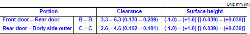
Check the clearance and surface height between front door and each part by visually and touching.
If the clearance and the surface height are out of specification, adjust them according to the procedures shown below.
FITTING ADJUSTMENT PROCEDURE
1. Remove center pillar lower garnish. Refer to INT-20, "CENTER PILLAR LOWER GARNISH : Removal and Installation".
2. Loosen door hinge mounting nuts on door side.
3. Adjust the surface height of rear door according to the fitting standard dimension.
4. Temporarily tighten door hinge mounting nuts on door side.
5. Loosen door hinge mounting nuts and bolts on body side.
6. Raise rear door at rear end to adjust clearance of rear door according to the fitting standard dimension.
7. After adjustment tighten bolts and nuts to the specified torque.
CAUTION:
• After installation, apply touch-up paint (the body color) onto the head of
hinge mounting bolts
and nuts.
• Check door hinge rotating part for poor lubrication. If necessary, apply body grease.
8. Install center pillar lower garnish. Refer to INT-20, "CENTER PILLAR LOWER GARNISH : Removal and Installation".
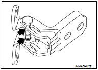
DOOR STRIKER ADJUSTMENT
Adjust door striker so that it becomes parallel with door lock insertion direction.
Door striker
DOOR STRIKER : Removal and Installation
REMOVAL
Remove TORX bolts, and then remove door striker.
INSTALLATION
Note the following items, and install in the reverse order of removal.
CAUTION:
• Check rear door open/close, lock/unlock operation after installation.
• After installation, be sure to perform the fitting adjustment. Refer to DLK-575, "DOOR ASSEMBLY : Adjustment".
Door hinge
DOOR HINGE : Removal and Installation
CAUTION:
• Perform work with 2 workers, because of it’s heavy weight.
• When removing and installing rear door assembly, support door with a jack and shop cloth to protect door and body.
REMOVAL
1. Remove rear door assembly. Refer to DLK-573, "DOOR ASSEMBLY : Removal and Installation".
2. Remove center pillar lower garnish. Refer to INT-20, "CENTER PILLAR LOWER GARNISH : Removal and Installation".
3. Remove rear door hinge mounting bolts and nuts (body side), and then remove door hinge.
INSTALLATION
Note the following items, and install in the reverse order of removal.
CAUTION:
• Apply anticorrosive agent onto the mounting surface.
• Check rear door open/close operation after installation.
• When removing and installing rear door assembly, perform the fitting adjustment. Refer to DLK-575, "DOOR ASSEMBLY : Adjustment".
• After installing, apply the touch-up paint (the body color) onto the head of door hinge mounting nuts.
• Check door hinge rotating part for poor lubrication. If necessary, apply body grease.
 : Grease up point
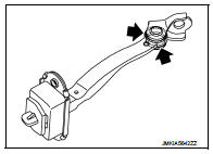
Door check link
DOOR CHECK LINK : Removal and Installation
REMOVAL
1. Fully close the rear door window.
2. Remove rear door finisher. Refer to INT-16, "Removal and Installation".
3. Remove mounting bolts of rear door speaker, and then remove rear door speaker.
4. Disconnect harness connector of rear door speaker.
5. Remove mounting bolt of the check link on the vehicle.
6. Remove mounting bolts of the check link on door panel.
7. Take door check link (1) out from the hole of door panel (2).
INSTALLATION
Note the following items, and install in the reverse order of removal.
CAUTION:
• Check rear door open/close operation after installation.
• Check door check link rotating part for poor lubrication. If necessary, apply grease.
 : Grease up point
 Front door
Exploded View
1. Front door panel
2. Grommet
3. TORX bolt
4. Door striker
5. Door pad
6. Bumper rubber
7. Door check link
8. Door hinge (lower)
9. Door hinge (upper)
10. Grommet
: D ...
 Back door
Exploded View
REMOVAL
1. Back door weather-strip
2. Back door stay
3. Back door stay lower bracket
4. Bumper rubber
5. Back door striker
6. Back door panel
7. Back door hinge
8. Hole c ...
Other materials:
Power supply routing circuit
Wiring Diagram - Battery power supply -
For connector terminal arrangements, harness layouts, and alphabets in a
(option abbreviation; if not
described in wiring diagram), refer to GI-12, "Connector Information/Explanation
of Option Abbreviation".
Wiring Diagram - Accessory p ...
ECU diagnosis information
ECM
Reference Value
VALUES ON THE DIAGNOSIS TOOL
Remarks:
• Specification data are reference values.
• Specification data are output/input values which are detected or supplied by
the ECM at the connector.
*Specification data may not be directly related to their components
signals/values/o ...
Basic inspection
DIAGNOSIS AND REPAIR WORKFLOW (METER SYSTEM)
Work flow
OVERALL SEQUENCE
• Reference 1···MWI-22, "On Board Diagnosis Function".
• Reference 2···MWI-36, "DTC Index".
• Reference 3···MWI-51, "COMBINATION METER : Diagnosis Procedure".
DETAILED FLOW
1.OBTAIN INFOR ...
