Nissan Juke Service and Repair Manual : Rear disc brake
Brake pad : Inspection and Adj
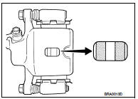
INSPECTION
Check brake pad wear thickness from an inspection hole on cylinder body. Check using a scale if necessary.
Wear thickness : Refer to BR-137, "Rear Disc Brake".
ADJUSTMENT
Burnish contact surfaces between disc rotor and brake pads according to the following procedure after refinishing or replacing brake pads, or if a soft pedal occurs at very low mileage.
CAUTION:
• Be careful of vehicle speed because the brake does not operate firmly/securely
until pads and disc
rotor are securely fitted.
• Only perform this procedure under safe road and traffic conditions. Use extreme caution.
1. Drive vehicle on straight, flat road.
2. Depress brake pedal with the power to stop vehicle within 3 to 5 seconds until the vehicle stops.
3. Drive without depressing brake for a few minutes to cool the brake.
4. Repeat steps 1 to 3 until pad and disc rotor are securely fitted.
Disc rotor : Inspection and Adjustment
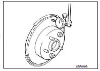
INSPECTION
Appearance
Check surface of disc rotor for uneven wear, cracks, and serious damage. Replace
it if necessary.
• 2WD: Refer to RAX-5, "Removal and Installation".
• 4WD: Refer to RAX-14, "Removal and Installation".
Runout
1. Fix the disc rotor to the wheel hub and bearing assembly with
wheel nuts (2 points at least).
2. Check the wheel bearing axial end play before the inspection.
• 2WD: Refer to RAX-4, "Inspection".
• 4WD: Refer to RAX-12, "Inspection".
3. Inspect the runout with a dial indicator to measure at 10 mm (0.39 in) inside the disc edge.
Runout (with it attached to the vehicle) : Refer to BR-137, "Rear Disc Brake".
4. Find the installation position that has a minimum runout by shifting the disc rotor-to-wheel hub and bearing assembly installation position by one hole at a time if the runout exceeds the limit value.
• Refinish the disc rotor if the runout is outside the limit even after performing the above operation.
CAUTION:
• Check in advance that the thickness of the disc rotor is wear thickness + 0.3
mm (0.012 in) or more.
• If the thickness is less than wear thickness + 0.3 mm (0.012 in), replace the disc rotor.
- 2WD: Refer to RAX-5, "Removal and Installation".
- 4WD: Refer to RAX-14, "Removal and Installation".
Wear thickness : Refer to BR-137, "Rear Disc Brake".
Thickness
Check the thickness of the disc rotor using a micrometer. Replace
the disc rotor if the thickness is below the wear limit.
• 2WD: Refer to RAX-5, "Removal and Installation".
• 4WD: Refer to RAX-14, "Removal and Installation".
Wear thickness : Refer to BR-137, "Rear Disc Brake".
ADJUSTMENT
Burnish contact surfaces between disc rotors and brake pads according to the following procedure after refinishing or replacing disc rotor, or if a soft pedal occurs at very low mileage.
CAUTION:
• Be careful of vehicle speed because the brake does not operate firmly/securely
until pad and disc
rotor are securely fitted.
• Only perform this procedure under safe road and traffic conditions. Use extreme caution.
1. Drive vehicle on straight, flat road.
2. Depress brake pedal with the power to stop vehicle within 3 to 5 seconds until the vehicle stops.
3. Drive without depressing brake for a few minutes to cool the brake.
4. Repeat steps 1 to 3 until pad and disc rotor are securely fitted.
 Front disc brake
Brake pad : Inspection and Adjustment
INSPECTION
Check brake pad wear thickness from an inspection hole on cylinder
body. Check using a scale if necessary.Wear thickness : Refer to BR-137, "Fr ...

Other materials:
Operation inspection
Work Procedure
The purpose of the operational check is to check that the individual system
operates normally.
Check condition : Engine running at normal operating temperature.
1.CHECK BLOWER MOTOR
1. Operate fan control dial.
2. Check that fan speed changes. Check operation for all fan speeds ...
Component parts
INTERIOR LIGHTING SYSTEM
INTERIOR LIGHTING SYSTEM : Component Parts Location
1. IPDM E/R
Refer to PCS-5, "Component Parts
Location"
2. BCM
Refer to BCS-6, "BODY CONTROL
SYSTEM : Component Parts Location"
3. Door lock and unlock switch
4. Front door request switch (driv ...
Fillet molding
Exploded View
1. Grommet
2. Clip
3. Clip
4. Front fillet molding
5. Rear fillet molding
: Pawl
: Do not reuse
Front fillet molding
FRONT FILLET MOLDING : Removal and Installation
REMOVAL
1. Remove front fillet molding fixing clips.
2. Remove front fillet molding front side fixing pa ...
