Nissan Juke Service and Repair Manual : PTC branch line circuit
Diagnosis Procedure
1.CHECK CONNECTOR
1. Turn the ignition switch OFF.
2. Disconnect the battery cable from the negative terminal.
3. Check the terminals and connectors of the PTC heater control unit for damage, bend and loose connection (unit side and connector side).
Is the inspection result normal? YES >> GO TO 2.
NO >> Repair the terminal and connector.
2.CHECK HARNESS FOR OPEN CIRCUIT
1. Disconnect the connector of PTC heater control unit.
2. Check the resistance between the PTC heater control unit harness connector terminals.
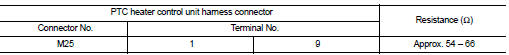
Is the measurement value within the specification? YES >> GO TO 3.
NO >> Repair the PTC heater control unit branch line.
3.CHECK POWER SUPPLY AND GROUND CIRCUIT
Check the power supply and the ground circuit of the PTC heater control unit. Refer to HAC-280, "PTC HEATER CONTROL UNIT : Diagnosis Procedure".
Is the inspection result normal? YES (Present error)>>Replace the PTC heater control unit. Refer to HAC.
YES (Past error)>>Error was detected in the PTC heater control unit branch line.
NO >> Repair the power supply and the ground circuit.
 MDU branch line circuit
Diagnosis Procedure
1.CHECK CONNECTOR
1. Turn the ignition switch OFF.
2. Disconnect the battery cable from the negative terminal.
3. Check the terminals and connectors of the multi display unit f ...
 BCM branch line circuit
Diagnosis Procedure
1.CHECK CONNECTOR
1. Turn the ignition switch OFF.
2. Disconnect the battery cable from the negative terminal.
3. Check the terminals and connectors of the BCM for damage, bend ...
Other materials:
P1554 battery current sensor
DTC Logic
DTC DETECTION LOGIC
DTC CONFIRMATION PROCEDURE
1.PERFORM COMPONENT FUNCTION CHECK
Perform component function check. Refer to EC-337, "Component Function
Check".
NOTE:
Use component function check to check the overall function of the battery
current sensor circuit. D ...
Mainshaft and gear
Exploded View
1. Mainshaft front bearing outer
race
2. Mainshaft front bearing inner race
3. Mainshaft
4. 1st main gear
5. 1st inner baulk ring
6. 1st synchronizer cone
7. 1st outer baulk ring
8. 1st-2nd coupling sleeve
9. Insert key
10. 1st-2nd synchronizer hub
11. 2nd outer baulk ...
Super lock does not operate
All door
ALL DOOR : Diagnosis Procedure
1.CHECK SUPER LOCK ACTUATOR
Check front driver side super lock actuator.
Refer to DLK-99, "DRIVER SIDE : Component Function Check".
Is the inspection result normal?
YES >> GO TO 2.
NO >> Repair or replace the malfunctioning p ...
