Nissan Juke Service and Repair Manual : Preparation
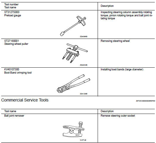
Special Service Tools
BASIC INSPECTION
STEERING WHEEL
Inspection
NEUTRAL POSITION STEERING WHEEL
1. Make sure that steering gear assembly, steering column assembly and steering wheel are installed in the correct position.
2. Perform neutral position inspection after wheel alignment. Refer to FSU-7, "Inspection".
3. Set vehicle to the straight-ahead position and confirm steering wheel is in the neutral position.
4. Loosen outer socket lock nut and turn inner socket to left and right equally to make fine adjustments if steering wheel is not in the neutral position.
STEERING WHEEL TURNING FORCE
1. Park vehicle on a level and dry surface, set parking brake.
2. Tires need to be inflated normal pressure. Refer to WT-9, "Tire Air Pressure".
3. Start engine.
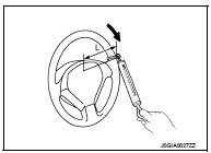
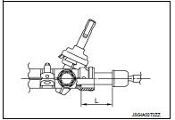
4. Check steering wheel turning force when steering wheel has been turned 360° from neutral position.
Steering wheel turning force : Refer to ST-23, "Steering Wheel Turning Force".
L : 185 mm (7.28 in)
NOTE
:
Multiply the distance from the hook of spring balance to the center
of steering wheel by the measurement value with a spring
balance.
FRONT WHEEL TURNING ANGLE
1. Check front wheel turning angle after toe-in inspection. Refer to FSU-7, "Inspection".
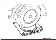
2. Place front wheels on turning radius gauges and rear wheels on stands, so that vehicle can be level.
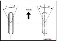
3. Check the maximum inner and outer wheel turning angles for LH and RH road wheels.
4. With the engine at idle, turn steering wheel from full left stop to full right stop and measure the turning angles.
Inner wheel (Angle: A) : Refer to ST-23, "Steering Angle".
Outer wheel (Angle: B) : Refer to ST-23, "Steering Angle".
5. Check the following items when turning angle is out of the standard.
a. Check rack stroke (L).
L : Refer to ST-23, "Rack Stroke".
b. If rack stroke is out of specification, replace steering gear assembly.
• Steering angles are not adjustable. Check steering gear assembly, steering column assembly, and front suspension components for wear or damage if any of the turning angles are different from the specified value. Replace any of them, if any non-standard condition exists.
 Service Notice or Precautions for Steering System
• In case of removing steering gear assembly, make the final tightening with
grounded and unloaded vehicle
condition, and then check wheel alignment.
• Observe the following precautions when disas ...
 Symptom diagnosis
NOISE, VIBRATION AND HARSHNESS (NVH) TROUBLESHOOTING
NVH Troubleshooting Chart
Use the chart below to find the cause of the symptom. If necessary, repair or
replace these parts.
×: Applic ...
Other materials:
Additional service when replacing transaxle assembly
Description
Perform the following work after the transaxle assembly is replaced.
CHECK LOADING OF CALIBRATION DATA
• The TCM acquires calibration data (individual characteristic value) of each
solenoid that is stored in the
ROM assembly (in the control valve). This enables the TCM to perform ...
Front drive shaft boot
Exploded View
1. Circular clip
2. Dust shield
3. Housing assembly
4. Boot band
5. Boot
6. Damper band
7. Dynamic damper
8. Circular clip
9. Joint sub-assembly
: Wheel side
: Fill NISSAN Genuine grease or
equivalent.
: Always replace after every
disassembly.
RIGHT SIDE
1. ...
Super lock actuator
Driver side : Component Function Check
1.CHECK FUNCTION
1. Select “DOOR LOCK” of “BCM” using CONSULT-III.
2. Select “SUPER LOCK” in “ACTIVE TEST” mode.
3. Check that the function operates normally according to the following
conditions.
Is the inspection result normal?
YES >> Super lo ...
