Nissan Juke Service and Repair Manual : Precautions For Refrigerant System Service
GENERAL REFRIGERANT PRECAUTION
WARNING:
• Never breathe A/C refrigerant and lubricant vapor or mist. Exposure may
irritate eyes, nose and
throat. Use only approved recovery/recycling equipment to discharge HFC-134a
(R-134a) refrigerant.
Ventilate work area before resuming service if accidental system discharge occurs. Additional health and safety information may be obtained from refrigerant and lubricant manufacturers.
• Never release refrigerant into the air. Use approved recovery/recycling recharging equipment to capture the refrigerant each time an air conditioning system is discharged.
• Wear always eye and hand protection (goggles and gloves) when working with any refrigerant or air conditioning system.
• Never store or heat refrigerant containers above 52°C (126°F).
• Never heat a refrigerant container with an open flame; Place the bottom of the container in a warm pail of water if container warming is required.
• Never intentionally drop, puncture, or incinerate refrigerant containers.
• Keep refrigerant away from open flames: poisonous gas is produced if refrigerant burns.
• Refrigerant displaces oxygen, therefore be certain to work in well ventilated areas to prevent suffocation.
• Never pressure test or leakage test HFC-134a (R-134a) service equipment and/or vehicle air conditioning systems with compressed air during repair. Some mixtures of air and HFC-134a (R-134a) have been shown to be combustible at elevated pressures. These mixtures, if ignited, may cause injury or property damage. Additional health and safety information may be obtained from refrigerant manufacturers.
WORKING WITH HFC-134a (R-134a)
CAUTION:
• CFC-12 (R-12) refrigerant and HFC-134a (R-134a) refrigerant are not
compatible. These regrigerants
must never be mixed, even in the smallest amounts. Compressor malfunction is
likely occur if the
refrigerants are mixed.
• Use only specified lubricant for the HFC-134a (R-134a) A/C system and HFC-134a (R-134a) components.
Compressor malfunction is likely to occur if lubricant other than that specified is used.
• The specified HFC-134a (R-134a) lubricant rapidly absorbs moisture from the atmosphere. The following handling precautions must be observed: - Cap (seal) immediately the component to minimize the entry of moisture from the atmosphere when removing refrigerant components from a vehicle.
- Never remove the caps (unseal) until just before connecting the components when installing refrigerant components to a vehicle. Connect all refrigerant loop components as quickly as possible to minimize the entry of moisture into system.
- Use only the specified lubricant from a sealed container. Reseal immediately containers of lubricant.
Lubricant becomes moisture saturated and should not be used without proper sealing.
- Never allow lubricant (A/C sysytem Oil Type R) to come in contact with styrene foam parts. Damage may result.
REFRIGERANT CONNECTION
A new type refrigerant connection has been introduced to all refrigerant lines except the following location.
• Expansion valve to evaporator • Refrigerant pressure sensor to liquid tank
WARNING:
Check that all refrigerant is discharged into the recycling equipment and the
pressure in the system is
less than atmospheric pressure. Then gradually loosen the discharge side hose
fitting and remove it.
CAUTION:
Observe the following when replacing or cleaning refrigerant cycle components.
• Store it in the same way at it is when mounted on the car when the compressor is removed. Failure to do so will cause lubricant to enter the low-pressure chamber.
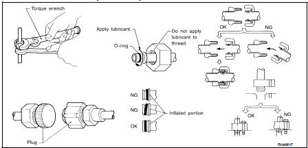
• Use always a torque wrench and a back-up wrench when connecting tubes.
• Plug immediately all openings to prevent entry of dust and moisture after disconnecting tubes.
• Connect the pipes at the final stage of the operation when installing an air conditioner in the vehicle.
Never remove the seal caps of pipes and other components until just before required for connection.
• Allow components stored in cool areas to warm to working area temperature before removing seal caps. This prevents condensation from forming inside A/C components.
• Remove thoroughly moisture from the refrigeration system before charging the refrigerant.
• Replace always used O-rings.
• Apply lubricant to circle of the O-rings shown in illustration when connecting tube. Be careful not to apply lubricant to threaded portion.
Name : A/C System Oil Type R
• O-ring must be closely attached to the groove portion of tube.
• Be careful not to damage O-ring and tube when replacing the O-ring.
• Connect tube until a click can be heard. Then tighten the nut or bolt by hand. Check that the O-ring is installed to tube correctly.
• Perform leakage test and make sure that there is no leakage from connections after connecting line.
Disconnect that line and replace the O-ring when the refrigerant leaking point is found. Then tighten connections of seal seat to the specified torque.
COMPRESSOR
CAUTION:
• Plug all openings to prevent moisture and foreign matter from entering.
• Store it in the same way at it is when mounted on the car when the compressor is removed.
• Follow “MAINTENANCE OF LUBRICANT LEVEL IN COMPRESSOR” exactly when replacing or repairing compressor. Refer to HA-74, "Description".
• Keep friction surfaces between clutch and pulley clean. Wipe it off by using a clean waste cloth moistened with thinner if the surface is contaminated with lubricant.
• Turn the compressor shaft by hand more than five turns in both directions after compressor service operation. This distributes equally lubricant inside the compressor. Let the engine idle and operate the compressor for one hour after the compressor is installed.
• Apply voltage to the new one and check for normal operation after replacing the compressor magnet clutch.
LEAK DETECTION DYE
CAUTION:
• The A/C system contains a fluorescent leak detection dye used for locating
refrigerant leakages. An
ultraviolet (UV) lamp is required to illuminate the dye when inspecting for
leakages.
• Wear always fluorescence enhancing UV safety goggles to protect eyes and enhance the visibility of the fluorescent dye.
• The fluorescent dye leak detector is not a replacement for an electrical leak detector. The fluorescent dye leak detector should be used in conjunction with an electrical leak detector to pin-point refrigerant leakages.
• Read and follow all manufacture’s operating instructions and precautions prior to performing the work for the purpose of safety and customer’s satisfaction.
• A compressor shaft seal should not necessarily be repaired because of dye seepage. The compressor shaft seal should only be repaired after confirming the leakage with an electrical leak detector.
• Remove always any remaining dye from the leakage area after repairs are completed to avoid a misdiagnosis during a future service.
• Never allow dye to come into contact with painted body panels or interior components. Clean immediately with the approved dye cleaner if dye is spilled. Fluorescent dye left on a surface for an extended period of time cannot be removed.
• Never spray the fluorescent dye cleaning agent on hot surfaces (engine exhaust manifold, etc.).
• Never use more than one refrigerant dye bottle [1/4 ounce (7.4 cc)] per A/C system.
• Leak detection dyes for HFC-134a (R-134a) and CFC-12 (R-12) A/C systems are different. Never use HFC-134a (R-134a) leak detection dye in CFC-12 (R-12) A/C system, or CFC-12 (R-12) leak detection dye in HFC-134a (R-134a) A/C system, or A/C system damage may result.
• The fluorescent properties of the dye remains for three or more years unless a compressor malfunction occurs.
NOTE:
Identification
• Vehicles with factory installed fluorescent dye have a green label.
• Vehicles without factory installed fluorescent dye have a blue label.
 Precaution for Procedure without Cowl Top Cover
When performing the procedure after removing cowl top cover, cover
the lower end of windshield with urethane, etc. ...
 Service Equipment
RECOVERY/RECYCLING RECHARGING EQUIPMENT
Be certain to follow the manufacturer’s instructions for machine operation
and machine maintenance. Never
introduce any refrigerant other than that specifie ...
Other materials:
Power supply and ground circuit
MULTI DISPLAY UNIT
MULTI DISPLAY UNIT : Diagnosis Procedure
1.CHECK FUSES
Check if any of the following fuses are blown:
Is the check result normal?
YES >> GO TO 2.
NO >> Replace fuse with a new one after repairing the applicable circuit.
2.CHECK POWER SUPPLY CIRCUIT
Check ...
Wiring diagram
AUTOMATIC AIR CONDITIONING SYSTEM
Wiring Diagram
For connector terminal arrangements, harness layouts, and alphabets in a
(option abbreviation; if not
described in wiring diagram), refer to GI-12, "Connector Information/Explanation
of Option Abbreviation".
...
Fog light switch (if so equipped)
To turn the fog lights on, turn the headlight switch to the
position, then turn the switch to the
position. To turn them off, turn the
switch to the OFF position.
The headlights must be on for the fog lights to operate.
When the headlight switch is in the AUTO position, turning the fog lig ...
