Nissan Juke Service and Repair Manual : Power supply and ground circuit
Diagnosis Procedure
1.CHECK FUSE
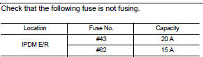
Is the fuse fusing? YES >> Replace the fuse after repairing the applicable circuit.
NO >> GO TO 2.
2.CHECK GROUND CONNECTION
1. Turn ignition switch OFF.
2. Check ground connection E21 and E38. Refer to GI-44, "Circuit Inspection".
Is the inspection result normal? YES >> GO TO 3.
NO >> Repair or replace ground connection.
3.CHECK ECM GROUND CIRCUIT
1. Disconnect ECM harness connectors.
2. Check the continuity between ECM harness connector and ground.
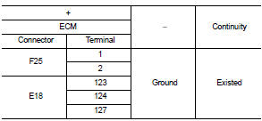
Is the inspection result normal? YES >> GO TO 4.
NO >> Repair or replace error-detected parts.
4.CHECK ECM POWER SUPPLY (MAIN)-I
1. Reconnect ECM harness connector.
2. Turn ignition switch ON.
3. Check the voltage between ECM harness connector terminals.
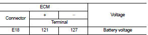
Is the inspection result normal? YES >> GO TO 5.
NO >> GO TO 6.
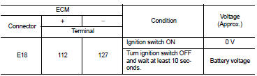
5.CHECK ECM POWER SUPPLY (MAIN)-II
1. Turn ignition switch OFF and wait at least 10 seconds.
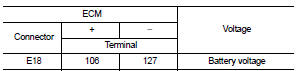
2. Check the voltage between ECM harness connector terminals as per the following.
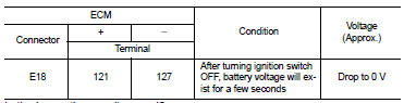
Is the inspection result normal? YES >> GO TO 9.
NO >> GO TO 7.
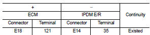
6.CHECK ECM POWER SUPPLY (MAIN) CIRCUIT
1. Turn ignition switch OFF.
2. Disconnect ECM harness connectors.
3. Disconnect IPDM E/R harness connector.
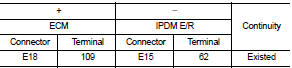
4. Check the continuity between ECM harness connector and IPDM E/R harness connector.
5. Also check harness for short to ground.
Is the inspection result normal? YES >> Perform the trouble diagnosis for power supply circuit.
NO >> Repair or replace error-detected parts.
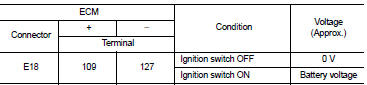
7.CHECK ECM RELAY CONTROL SIGNAL
Check the voltage between ECM harness connector terminals as per the following.
Is the inspection result normal? YES >> Check Intermittent Incident. Refer to GI-42, "Intermittent Incident".
NO >> GO TO 8.
8.CHECK ECM RELAY CONTROL SIGNAL CIRCUIT
1. Turn ignition switch OFF.
2. Disconnect ECM harness connector.
3. Disconnect IPDM E/R harness connector.
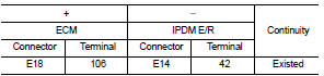
4. Check the continuity between ECM harness connector and IPDM E/R harness connector.
5. Also check harness for short to ground and to power.
Is the inspection result normal? YES >> Replace IPDM E/R. Refer to PCS-34, "Removal and Installation".
NO >> Repair or replace error-detected parts.
9.CHECK IGNITION SWITCH SIGNAL
Is the inspection result normal? YES >> GO TO 11.
NO >> GO TO 10.
10.CHECK IGNITION SWITCH SIGNAL CIRCUIT
1. Turn ignition switch OFF.
2. Disconnect ECM harness connector.
3. Disconnect IPDM E/R harness connector.
4. Check the continuity between ECM harness connector and IPDM E/R harness connector.
5. Also check harness for short to ground and to power.
Is the inspection result normal? YES >> Perform the trouble diagnosis for power supply circuit.
NO >> Repair or replace error-detected parts.
11.CHECK ECM POWER SUPPLY (BACK-UP)
Check the voltage between ECM harness connector terminals.
Is the inspection result normal? YES >> Check Intermittent Incident. Refer to GI-42, "Intermittent Incident".
NO >> GO TO 12.
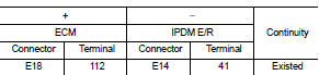
12.CHECK ECM POWER SUPPLY (BACK-UP) CIRCUIT
1. Turn ignition switch OFF.
2. Disconnect ECM harness connector.
3. Disconnect IPDM E/R harness connector.
4. Check the continuity between ECM harness connector and IPDM E/R harness connector.
5. Also check harness for short to ground.
Is the inspection result normal? YES >> Perform the trouble diagnosis for power supply circuit.
NO >> Repair or replace error-detected parts.
 Trouble diagnosis - specification
value
Trouble diagnosis - specification
value
Description
The specification (SP) value indicates the tolerance of the value that is
displayed in “SPEC” of “DATA MONITOR”
mode of CONSULT-III during normal operation of the Engine Control Syste ...
 U0101 Can comm circuit
Description
CAN (Controller Area Network) is a serial communication line for real time
application. It is an on-vehicle multiplex
communication line with high data communication speed and excelle ...
Other materials:
Precaution
Precautions for Suspension
• When installing rubber bushings, the final tightening must be carried out
under unladen conditions with tires
on ground. Spilled oil might shorten the life of rubber bushings. Be sure to
wipe off any spilled oil.
- Unladen conditions mean that fuel, engine coolant ...
Hood switch
Component Function Check
1.CHECK FUNCTION
1. Select “HOOD SW” in “Data Monitor” mode of “IPDM E/R” using CONSULT-III.
2. Check “HOOD SW” indication under the following condition.
Is the indication normal?
YES >> Hood switch is OK.
NO >> Go to SEC-223, "Diagnosis Procedure& ...
Corrosion protection
Description
To provide improved corrosion prevention, the following anti-corrosive
measures have been implemented in
NISSAN production plants. When repairing or replacing body panels, it is
necessary to use the same anti-corrosive
measures.
ANTI-CORROSIVE PRECOATED STEEL (GALVANNEALED STEE ...
