Nissan Juke Service and Repair Manual : Power supply and ground circuit
Diagnosis Procedure
1.CHECK ABS ACTUATOR AND ELECTRIC UNIT (CONTROL UNIT) IGNITION POWER SUPPLY
1. Turn the ignition switch OFF.
2. Disconnect ABS actuator and electric unit (control unit) harness connector.
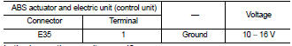
3. Check voltage between ABS actuator and electric unit (control unit) harness connector and ground.
4. Turn the ignition switch ON
CAUTION:
Never start engine
.
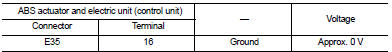
5. Check voltage between ABS actuator and electric unit (control unit) harness connector and ground.

Is the inspection result normal? YES >> GO TO 3.
NO >> GO TO 2.
2.CHECK ABS ACTUATOR AND ELECTRIC UNIT (CONTROL UNIT) IGNITION POWER SUPPLY CIRCUIT
1. Turn the ignition switch OFF.
2. Check 10 A fuse (#57).
3. Disconnect IPDM E/R harness connector.
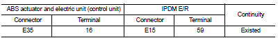
4. Check continuity between ABS actuator and electric unit (control unit) harness connector and IPDM E/R harness connector
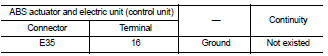
5. Check for continuity between ABS actuator and electric unit (control unit) harness connector and the ground.
Is the inspection result normal? YES >> Perform trouble diagnosis for ignition power supply. Refer to PG-15, "Wiring Diagram - IGNITION POWER SUPPLY -".
NO >> Repair or replace error-detected parts.
3.CHECK MOTOR AND MOTOR RELAY POWER SUPPLY
1. Turn the ignition switch OFF.
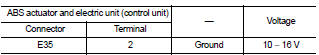
2. Check voltage between ABS actuator and electric unit (control unit) harness connector and ground.
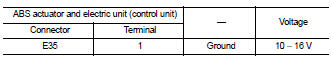
3. Turn the ignition switch ON.
CAUTION:
Never start engine.
4. Check voltage between ABS actuator and electric unit (control unit) harness connector and ground.
Is the inspection result normal? YES >> GO TO 5.
NO >> GO TO 4.
4.CHECK MOTOR AND MOTOR RELAY POWER SUPPLY CIRCUIT
1. Turn the ignition switch OFF.
2. Check 30 A fusible link (K).
3. Check continuity and short circuit between ABS actuator and electric unit (control unit) harness connector terminal (1) and 30 A fusible link (K).
Is the inspection result normal? YES >> Perform trouble diagnosis for battery power supply. Refer to PG-10, "Wiring Diagram - BATTERY POWER SUPPLY -".
NO >> Repair or replace error-detected parts.
5.CHECK ACTUATOR RELAY, ABS IN VALVE, ABS OUT VALVE POWER SUPPLY
1. Turn the ignition switch OFF.
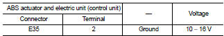
2. Check voltage between ABS actuator and electric unit (control unit) harness connector and ground.
3. Turn the ignition switch ON
CAUTION:
Never start engine.
4. Check voltage between ABS actuator and electric unit (control unit) harness connector and ground.
Is the inspection result normal? YES >> GO TO 7.
NO >> GO TO 6.
6.CHECK ACTUATOR RELAY, ABS IN VALVE, ABS OUT VALVE POWER SUPPLY CIRCUIT
1. Turn the ignition switch OFF.
2. Check 50 A fusible link (I).
3. Check continuity and short circuit between ABS actuator and electric unit (control unit) harness connector terminal (2) and 50 A fusible link (I).
Is the inspection result normal? YES >> Perform trouble diagnosis for battery power supply. Refer to PG-10, "Wiring Diagram - BATTERY POWER SUPPLY -".
NO >> Repair or replace error-detected parts.
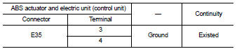
7.CHECK ABS ACTUATOR AND ELECTRIC UNIT (CONTROL UNIT) GROUND CIRCUIT
Check for continuity between ABS actuator and electric unit (control unit) harness connector and the ground.
Is the inspection result normal? YES >> GO TO 8.
NO >> Repair or replace error-detected parts.
8.CHECK TERMINAL
• Check ABS actuator and electric unit (control unit) pin terminals for damage or loose connection with harness connector.
• Check IPDM E/R pin terminals for damage or loose connection with harness connector.
Is the inspection result normal? YES >> INSPECTION END
NO >> Repair or replace error-detected parts.
 U1010 control unit (can)
Description
CAN (Controller Area Network) is a serial communication line for real time
application. It is an on-vehicle multiplex
communication line with high data communication speed and excellen ...
 Parking brake switch
Component Function Check
1.CHECK PARKING BRAKE SWITCH OPERATION
Operate the parking brake lever. Then check that the brake warning lamp in
the combination meter turns ON/
OFF correctly.
Is the ...
Other materials:
Rear window defogger switch
With auto A/C
WITH AUTO A/C : Description
• The rear window defogger is operated by turning the rear window defogger
switch ON.
• The indicator lamp in the rear window defogger switch illuminates when the
rear window defogger is operating.
WITH AUTO A/C : Component Function Check
1.CHECK RE ...
Power door lock system
System Diagram
System Description
DOOR LOCK FUNCTION
• The door lock and unlock switch (driver side) is build into power window
main switch.
• The door lock and unlock switch (passenger side) is build into front power
window switch (passenger side).
• Interlocked with the locking operatio ...
Water outlet
Exploded View
1. Engine coolant temperature sensor
2. Clamp
3. Gasket
4. Clamp
5. Bracket
6. Clamp
7. Water outlet
8. Clamp
9. Clamp
10. Washer
A. To electric throttle control actuator
B. To radiator
C. To CVT oil warmer
D. To heater core
E. To electric throttle control act ...
