Nissan Juke Service and Repair Manual : Power supply and ground circuit
Diagnosis Procedure
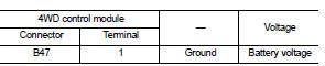
1.CHECK 4WD CONTROL MODULE POWER SUPPLY (1)
1. Turn the ignition switch OFF.
2. Disconnect 4WD control module harness connector.
3. Check the voltage between 4WD control module harness connector and ground.
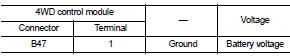
4. Turn the ignition switch ON.
CAUTION:
Never start the engine.
5. Check the voltage between 4WD control module harness connector and ground.
Is the inspection result normal? YES >> GO TO 3.
NO >> GO TO 2.
2.CHECK 4WD CONTROL MODULE POWER SUPPLY (2)
1. Turn the ignition switch OFF.
2. Check the 10A fuse (#33).
3. Check the harness for open or short between 4WD control module harness connector No.1 terminal and 10A (#33).
Is the inspection result normal? YES >> Perform the trouble diagnosis for power supply circuit. Refer to PG-10, "Wiring Diagram - BATTERY POWER SUPPLY -".
NO >> Repair or replace error-detected parts.
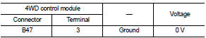
3.CHECK 4WD CONTROL MODULE POWER SUPPLY (3)
1. Turn the ignition switch OFF.
2. Check the voltage between 4WD control module harness connector and ground.
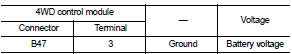
3. Turn the ignition switch ON.
CAUTION:
Never start the engine.
4. Check the voltage between 4WD control module harness connector and ground.
Is the inspection result normal? YES >> GO TO 5.
NO >> GO TO 4.
4.CHECK 4WD CONTROL MODULE POWER SUPPLY (4)
1. Turn the ignition switch OFF.
2. Check the 10A fuse (#3).
3. Check the harness for open or short between 4WD control module harness connector No.3 terminal and 10A (#3).
Is the inspection result normal? YES >> Perform the trouble diagnosis for ignition power supply circuit. Refer to PG-15, "Wiring Diagram - IGNITION POWER SUPPLY -".
NO >> Repair or replace error-detected parts.
5.CHECK 4WD SOLENOID POWER SUPPLY (1)
1. Turn the ignition switch OFF.
2. Disconnect 4WD control module harness connector.
3. Check the voltage between 4WD control module harness connector and ground.
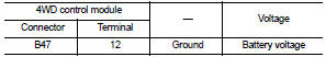
4. Turn the ignition switch OFF to ON.
CAUTION:
Never start the engine.
5. Check the voltage between 4WD control module harness connector and ground.
Is the inspection result normal? YES >> GO TO 7.
NO >> GO TO 6.
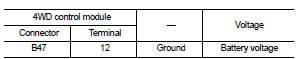
6.CHECK 4WD SOLENOID POWER SUPPLY (2)
1. Turn the ignition switch OFF.
2. Check the 10A fuse (#12).
3. Check the harness for open or short between 4WD control module harness connector No.12 and the 10A fuse (#12).
Is the inspection result normal? YES >> Perform the trouble the diagnosis for power supply circuit. Refer to PG-10, "Wiring Diagram - BATTERY POWER SUPPLY -".
NO >> Repair or replace error-detected parts.
7.CHECK 4WD CONTROL MODULE GROUND
1. Turn the ignition switch OFF.
2. Check the continuity between 4WD control module harness connector and ground.
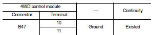
Is the inspection result normal? YES >> INSPECTION END
NO >> Repair or replace error-detected parts.
 U1010 control unit (CAN)
Description
CAN (Controller Area Network) is a serial communication line for real time
application. It is an on-vehicle multiplex
communication line with high data communication speed and excellen ...
 4WD warning lamp
Component Function Check
1.CHECK 4WD WARNING LAMP FUNCTION
1. Turn the ignition switch ON.
2. Check that 4WD warning lamp turns on.
Is the inspection result normal?
YES >> INSPECTION END
...
Other materials:
Service Equipment
RECOVERY/RECYCLING RECHARGING EQUIPMENT
Be certain to follow the manufacturer’s instructions for machine operation
and machine maintenance. Never
introduce any refrigerant other than that specified into the machine.
ELECTRICAL LEAK DETECTOR
Be certain to follow the manufacturer’s instruction ...
B2099 ignition relay off stuck
Description
• IPDM E/R operates the ignition relay when it receives an ignition switch ON
signal from BCM via CAN communication.
• Turn the ignition relay OFF by pressing the push-button ignition switch once
when the vehicle speed is 4 km/
h (2.5 MPH) or less.
• Turn the ignition relay OFF w ...
P1643 thermoplunger control unit
DTC Logic
DTC DETECTION LOGIC
Diagnosis Procedure
1.CHECK THERMOPLUNGER CONTROL UNIT POWER SUPPLY CIRCUIT
1. Turn ignition switch OFF.
2. Disconnect thermoplunger control unit harness connector.
3. Check the voltage between thermoplunger control unit harness connector and
ground.
Is the ...
