Nissan Juke Service and Repair Manual : P2135 TP sensor
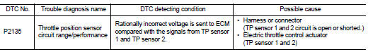
DTC Logic
DTC DETECTION LOGIC
NOTE
:
If DTC P2135 is displayed with DTC P0643, first perform the trouble diagnosis
for DTC P0643. Refer to
EC-686, "DTC Logic".
DTC CONFIRMATION PROCEDURE
1.PRECONDITIONING
If DTC Confirmation Procedure has been previously conducted, always turn ignition switch OFF and wait at least 10 seconds before conducting the next test.
TESTING CONDITION:
Before performing the following procedure, confirm that battery voltage is more
than 10 V at idle.
>> GO TO 2.
2.PERFORM DTC CONFIRMATION PROCEDURE
1. Start engine and let it idle for 1 second.
2. Check DTC.
Is DTC detected? YES >> Go to EC-755, "Diagnosis Procedure".
NO >> INSPECTION END
Diagnosis Procedure
1.CHECK GROUND CONNECTION
1. Turn ignition switch OFF.
2. Check ground connection E21 and E38. Refer to Ground Inspection in GI-44, "Circuit Inspection".
Is the inspection result normal? YES >> GO TO 2.
NO >> Repair or replace ground connection.
2.CHECK THROTTLE POSITION SENSOR POWER SUPPLY CIRCUIT
1. Disconnect electric throttle control actuator harness connector.
2. Turn ignition switch ON.
3. Check the voltage between electric throttle control actuator harness connector and ground.
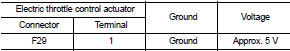
Is the inspection result normal? YES >> GO TO 3.
NO >> Repair open circuit or short to ground or short to power in harness or connectors.
3.CHECK THROTTLE POSITION SENSOR GROUND CIRCUIT FOR OPEN AND SHORT
1. Turn ignition switch OFF.
2. Disconnect ECM harness connector.
3. Check the continuity between electric throttle control actuator harness connector and ground.
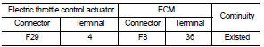
4. Also check harness for short to ground and short to power.
Is the inspection result normal? YES >> GO TO 4.
NO >> Repair open circuit or short to ground or short to power in harness or connectors.
4.CHECK THROTTLE POSITION SENSOR INPUT SIGNAL CIRCUIT FOR OPEN AND SHORT
1. Check the continuity between electric throttle control actuator harness connector and ground.
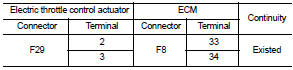
2. Also check harness for short to ground and short to power.
Is the inspection result normal? YES >> GO TO 5.
NO >> Repair open circuit or short to ground or short to power in harness or connectors.
5.CHECK THROTTLE POSITION SENSOR
Refer to EC-756, "Component Inspection".
Is the inspection result normal? YES >> GO TO 7.
NO >> GO TO 6.
6.REPLACE ELECTRIC THROTTLE CONTROL ACTUATOR
Replace electric throttle control actuator. Refer to EM-163, "Exploded View".
>> INSPECTION END
7.CHECK INTERMITTENT INCIDENT
Refer to GI-42, "Intermittent Incident".
>> INSPECTION END
Component Inspection
1.CHECK THROTTLE POSITION SENSOR
1. Turn ignition switch OFF.
2. Reconnect all harness connectors disconnected.
3. Perform EC-543, "Work Procedure".
4. Turn ignition switch ON.
5. Set selector lever to D (CVT) or 1st (M/T) position.
6. Check the voltage between ECM harness connector and ground.
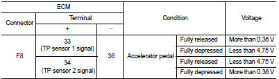
Is the inspection result normal? YES >> INSPECTION END
NO >> GO TO 2.
2.REPLACE ELECTRIC THROTTLE CONTROL ACTUATOR
Replace electric throttle control actuator. Refer to EM-163, "Exploded View".
>> INSPECTION END
 P2127, P2128 APP sensor
DTC Logic
DTC DETECTION LOGIC
DTC CONFIRMATION PROCEDURE
1.PRECONDITIONING
If DTC Confirmation Procedure has been previously conducted, always turn
ignition switch OFF and wait at
least 10 se ...
 P2138 APP sensor
DTC Logic
DTC DETECTION LOGIC
NOTE:
If DTC P2138 is displayed with DTC P0643, first perform the trouble diagnosis
for DTC P0643. Refer to
EC-686, "DTC Logic".
DTC CONFIRMATION PROCE ...
Other materials:
P0603 ECM
Description
ECM has the memory function of the DTC memory, the air-fuel ratio
feedback compensation value memory, the Idle Air Volume Learning
value memory, etc. even when the ignition switch is turned OFF.
DTC Logic
DTC DETECTION LOGIC
*: This self-diagnosis is not for ECM power supply ci ...
C1606 EPS motor
DTC Logic
DTC DETECTION LOGIC
DTC CONFIRMATION PROCEDURE
1.PRECONDITIONING
If “DTC CONFIRMATION PROCEDURE” has been previously conducted, always turn
ignition switch OFF and
wait at least 10 seconds before conducting the next test.
>> GO TO 2.
2.DTC REPRODUCTION PROCEDURE
With ...
On board diagnostic (OBD) system
Description
This is an onboard diagnosis system which records diagnosis information
related to the exhaust gases. It
detects malfunctions related to sensors and actuators. The malfunctions are
indicated by means of the malfunction
indicator lamp (MIL) and are stored as DTC in the ECU memory. ...
