Nissan Juke Service and Repair Manual : P1643 thermoplunger control unit
DTC Logic
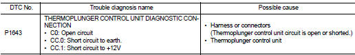
DTC DETECTION LOGIC
Diagnosis Procedure
1.CHECK THERMOPLUNGER CONTROL UNIT POWER SUPPLY CIRCUIT
1. Turn ignition switch OFF.
2. Disconnect thermoplunger control unit harness connector.
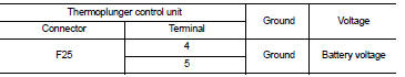
3. Check the voltage between thermoplunger control unit harness connector and ground.
Is the inspection result normal? YES >> GO TO 3.
NO >> GO TO 2.
2.DETECT MALFUNCTIONING PART
Check the following.
• 100A fusible link (letter B) • Harness for open and short between thermoplunger control unit and battery
>> Repair open circuit or short to ground or short to power in harness or connectors.
3.CHECK THERMOPLUNGER CONTROL UNIT GROUND CIRCUIT FOR OPEN AND SHORT
1. Disconnect ECM harness connector.
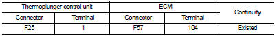
2. Check the continuity between thermoplunger control unit harness connector and ECM harness connector.
3. Also check harness for short to ground and short to power.
Is the inspection result normal? YES >> GO TO 4.
NO >> Repair open circuit or short to ground or short to power in harness or connectors.
4.CHECK INTERMITTENT INCIDENT
Refer to GI-42, "Intermittent Incident", ???INCIDENT SIMULATION TESTS??? and ???GROUND INSPECTION???.
Is the inspection result normal? YES >> Replace thermoplunger control unit.
NO >> Repair or replace.
 P1642 thermoplunger control unit
DTC Logic
DTC DETECTION LOGIC
Diagnosis Procedure
1.CHECK THERMOPLUNGER CONTROL UNIT POWER SUPPLY CIRCUIT
1. Turn ignition switch OFF.
2. Disconnect thermoplunger control unit harness connector ...
 P1650 thermoplunger control unit
DTC Logic
DTC DETECTION LOGIC
Diagnosis Procedure
1.CHECK THERMOPLUNGER CONTROL UNIT POWER SUPPLY CIRCUIT
1. Turn ignition switch OFF.
2. Disconnect thermoplunger control unit harness connector ...
Other materials:
A-bag branch line circuit
Diagnosis Procedure
WARNING:
• Before servicing, turn ignition switch OFF, disconnect battery negative
terminal, and wait 3 minutes
or more. (To discharge backup capacitor.)
• Never use unspecified tester or other measuring device.
1.CHECK CONNECTOR
1. Turn the ignition switch OFF.
2. Disco ...
Operation inspection
Work Procedure
The purpose of the operational check is to check that the individual system
operates normally.
Check condition : Engine running at normal operating temperature.
1.CHECK MEMORY FUNCTION
1. Set temperature to 30°C by operating the temperature control dial.
2. Press OFF switch.
3 ...
Fuel pressure control
Fuel pressure control : System Diagram
Fuel pressure controlL : System Description
INPUT/OUTPUT SIGNAL CHART
*: ECM determines the start signal status by the engine speed signal and
battery voltage.
CVT models
System Description
Low fuel pressure control
• The low fuel pressure pump i ...
