Nissan Juke Service and Repair Manual : P1614 chain of IMMU-KEY
DTC Logic
DTC DETECTION LOGIC
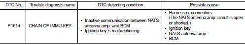
DTC CONFIRMATION PROCEDURE
1.PERFORM DTC CONFIRMATION PROCEDURE
1. Turn ignition switch ON.
2. Check DTC in “Self Diagnostic Result” mode of “ENGINE” using CONSULT-III.
Is DTC detected? YES >> Refer to SEC-195, "Diagnosis Procedure".
NO >> INSPECTION END
Diagnosis Procedure
1.CHECK FUSE
Check that the following IPDM E/R fuse is not blown.

Is the fuse fusing? YES >> Replace the blown fuse after repairing the affected circuit if a fuse is blown.
NO >> GO TO 2.
2.CHECK NATS ANTENNA AMP. INSTALLATION
Check NATS antenna amp. Installation. Refer to SEC-233, "Removal and Installation".
Is the inspection result normal? YES >> GO TO 3.
NO >> Reinstall NATS antenna amp. correctly.
3.CHECK IGNITION KEY
Start engine using another registered ignition key.
Does the engine start? YES-1 >> Replace ignition key.
YES-2 >> Perform initialization of BCM and registration of all ignition keys using CONSULT-III. For initialization and registration procedures, refer to CONSULT-III Operation Manual NATS-IVIS/NVIS.
NO >> GO TO 4.
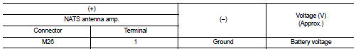
4.CHECK NATS ANTENNA AMP. POWER SUPPLY
1. Turn ignition switch OFF.
2. Disconnect NATS antenna amp. connector.
3. Check voltage between NATS antenna amp. harness connector and ground.
Is the inspection result normal? YES >> GO TO 6.
NO >> GO TO 5.
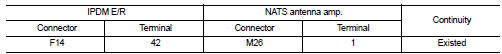
5.CHECK NATS ANTENNA AMP. POWER SUPPLY CIRCUIT
1. Disconnect IPDM E/R connector.
2. Check continuity between IPDM E/R harness connector and NATS antenna amp. connector.
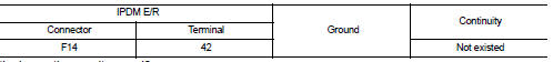
3. Check continuity between IPDM E/R harness connector and ground.
Is the inspection result normal? YES >> Replace IPDM E/R. Refer to PCS-63, "Removal and Installation".
NO >> Repair or replace harness.
6.CHECK NATS ANTENNA AMP. GROUND CIRCUIT
Check continuity between NATS antenna amp. harness connector and ground.
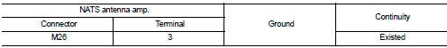
Is the inspection result normal? YES >> GO TO 7.
NO >> Repair or replace harness.
7.CHECK NATS ANTENNA AMP. SIGNAL
1. Connect BCM connector and NATS antenna amp. connector.
2. Check voltage between BCM harness connector and ground.
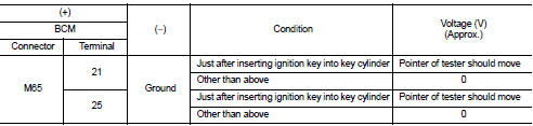
Is the inspection result normal? YES >> GO TO 9.
NO >> GO TO 8.
8.CHECK NATS ANTENNA AMP. SIGNAL CIRCUIT
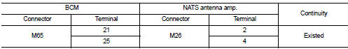
1. Disconnect NATS antenna amp. connector.
2. Check continuity between BCM harness connector and NATS antenna amp. harness connector.
3. Check continuity between BCM harness connector and ground.
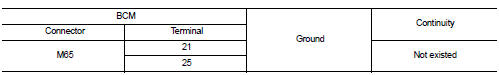
Is the inspection result normal? YES >> Replace NATS antenna amp. Refer to SEC-233, "Removal and Installation".
NO >> Repair or replace harness.
9.CHECK INTERMITTENT INCIDENT
Refer to GI-42, "Intermittent Incident".
>> INSPECTION END
 P1612 chain of ECM-IMMU
DTC Logic
DTC DETECTION LOGIC
NOTE:
• If DTC P1612 is displayed with DTC U1000 (for BCM), first perform the trouble
diagnosis for DTC U1000.
Refer to BCS-153, "DTC Logic".
• If DTC ...
 P1615 diffrence of key
DTC Logic
DTC DETECTION LOGIC
DTC CONFIRMATION PROCEDURE
1.PERFORM DTC CONFIRMATION PROCEDURE
1. Turn ignition switch ON.
2. Check DTC in “Self Diagnostic Result” mode of “ENGINE” using CONSULT ...
Other materials:
Combination switch input circuit
Diagnosis Procedure
1.CHECK INPUT 1 - 5 CIRCUIT FOR OPEN
1. Turn ignition switch OFF.
2. Disconnect BCM and combination switch connectors.
3. Check continuity between BCM harness connector and combination switch harness
connector.
Does continuity exist?
YES >> GO TO 2.
NO >> ...
System
System Description
Fan speed of blower motor is changed by the combination of fan control dial
(fan switch) operation and blower
fan resistor control.
Door Control
SWITCHES AND THEIR CONTROL FUNCTIONS
1. Intake door
2. Blower motor
3. Air conditioner filter
4. Max. cool door
5. Upper ...
LAN System can system (type 6)
DTC/CIRCUIT DIAGNOSIS
Main line between IPDM-E and DLC circuit
Diagnosis Procedure
1.CHECK CONNECTOR
1. Turn the ignition switch OFF.
2. Disconnect the battery cable from the negative terminal.
3. Check the following terminals and connectors for damage, bend and loose
connection (connector s ...
