Nissan Juke Service and Repair Manual : P1586 G sensor
DTC Logic
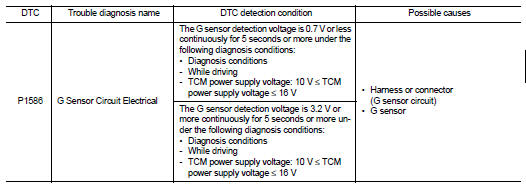
DTC DETECTION LOGIC
DTC CONFIRMATION PROCEDURE
CAUTION:
Be careful of the driving speed.
1.PREPARATION BEFORE WORK
If another "DTC CONFIRMATION PROCEDURE" occurs just before, turn ignition switch OFF and wait for at least 10 seconds, then perform the next test.
>> GO TO 2.
2.CHECK DTC DETECTION
 With CONSULT-III
1. Start the engine.
2. Drive the vehicle for 10 seconds or more.
3. Stop the vehicle.
4. Check the DTC.
Is “P1586” detected? YES >> Go to TM-435, "Diagnosis Procedure".
NO >> INSPECTION END
Diagnosis Procedure
1.CHECK G SENSOR SIGNAL
 With CONSULT-III
1. Park the vehicle on a level surface.
2. Turn ignition switch ON.
3. Select “Data Monitor” in “TRANSMISSION”.
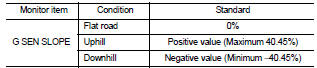
4. Select “G SEN SLOPE”.
5. Swing the vehicle and check if the value varies between −40.45% and 40.45%.
Is the inspection result normal?
YES >> GO TO 2.
NO >> GO TO 3.
2.G SENSOR CALIBRATION (PART 1)
 With CONSULT-III
1. Select “Self Diagnostic Results” in “TRANSMISSION”.
2. Touch “Erase”.
>> Perform "G SENSOR CALIBRATION". Refer to TM-377, "Procedure".
3.CHECK SENSOR POWER SUPPLY
1. Turn ignition switch OFF.
2. Disconnect the G sensor connector.
3. Turn ignition switch ON.
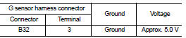
4. Check voltage between G sensor harness connector terminal and ground.
Is the inspection result normal? YES >> GO TO 4.
NO >> GO TO 8.
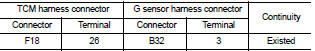
4.CHECK CIRCUIT BETWEEN TCM AND G SENSOR (PART 1)
1. Turn ignition switch OFF.
2. Disconnect the TCM connector.
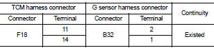
3. Check continuity between TCM harness connector terminals and G sensor harness connector terminals.
Is the inspection result normal? YES >> GO TO 5.
NO >> Repair or replace the malfunctioning parts.
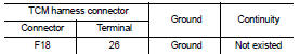
5.CHECK CIRCUIT BETWEEN TCM AND G SENSOR (PART 2)
Check the continuity between TCM harness connector terminals and ground.
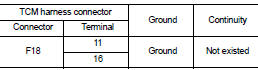
Is the inspection result normal? YES >> GO TO 6.
NO >> Repair or replace the malfunctioning parts.
6.CHECK G SENSOR
1. Remove the G sensor. TM-492, "Removal and Installation".
2. Connect the all connectors.
3. Turn ignition switch ON.
4. Check the voltage between TCM connector terminal and ground.
 : Direction of gravitational
force
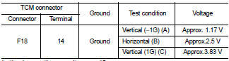
Is the inspection result normal? YES >> GO TO 7.
NO >> Replace G sensor.TM-492, "Removal and Installation".
7.G SENSOR CALIBRATION (PART 2)
With CONSULT-III
1. Install G sensor. TM-492, "Removal and Installation".
2. Select “Self Diagnostic Results” in “TRANSMISSION”.
3. Touch “Erase”.
>> Perform "G SENSOR CALIBRATION". Refer to TM-377, "Procedure".
8.CHECK SENSOR POWER SUPPLY CIRCUIT (PART 1)
1. Turn ignition switch OFF.
2. Disconnect the TCM connector.
3. Check continuity between TCM harness connector terminal and G sensor harness connector terminal.
Is the inspection result normal? YES >> GO TO 9.
NO >> Repair or replace the malfunctioning parts.
9.CHECK SENSOR POWER SUPPLY CIRCUIT (PART 2)
Check the continuity between TCM harness connector terminal and ground.
Is the inspection result normal? YES >> Check intermittent incident. Refer to GI-42, "Intermittent Incident".
NO >> Repair or replace the malfunctioning parts.
 P0963 pressure control solenoid A
DTC Logic
DTC DETECTION LOGIC
DTC CONFIRMATION PROCEDURE
1.PREPARATION BEFORE WORK
If another "DTC CONFIRMATION PROCEDURE" occurs just before, turn ignition
switch OFF and wait for a ...
 P1588 G sensor
DTC Logic
DTC DETECTION LOGIC
DTC CONFIRMATION PROCEDURE
CAUTION:
Be careful of the driving speed.
1.PREPARATION BEFORE WORK
If another "DTC CONFIRMATION PROCEDURE" occurs just befor ...
Other materials:
Precaution
Precaution for Supplemental Restraint System (SRS) "AIR BAG" and "SEAT
BELT
PRE-TENSIONER"
The Supplemental Restraint System such as “AIR BAG” and “SEAT BELT
PRE-TENSIONER”, used along
with a front seat belt, helps to reduce the risk or severity of injury to the
driver a ...
Low pressure fuel pump
M/T models : Component Function Check
1.CHECK FUEL PUMP FUNCTION
1. Turn ignition switch ON.
2. Pinch fuel feed hose with two fingers.
NOTE:
Fuel pressure pulsation should be felt on the fuel feed hose for 1 second after
ignition switch is turned ON.
Is the inspection result normal?
YES ...
Brake system
BRAKING PRECAUTIONS
The brake system has two separate hydraulic circuits. If one circuit malfunctions,
you will still have braking at two wheels.
You may feel a small click and hear a sound when the brake pedal is fully depressed
slowly.
This is not a malfunction and indicates that the brake ...
