Nissan Juke Service and Repair Manual : P1220 fuel pump control module (FPCM)
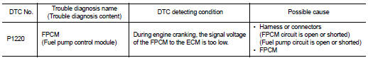
DTC Logic
DTC DETECTION LOGIC
DTC CONFIRMATION PROCEDURE
1.PRECONDITIONING
1. Turn ignition switch OFF and wait at least 10 seconds.
2. Turn ignition switch ON.
3. Turn ignition switch OFF and wait at least 10 seconds.
TESTING CONDITION:
• Before performing the following procedure, confirm that battery voltage is
between 12 - 15 V at idle.
• Before performing the following procedure, check that the engine coolant temperature is −10°C (14°F) or more.
>> GO TO 2.
2.PERFORM DTC CONFIRMATION PROCEDURE
1. Start engine and let it idle for at least 5 seconds.
If engine does not start, crank engine for at least 5 seconds.
2. Check DTC.
Is DTC detected? YES >> Proceed to EC-695, "Diagnosis Procedure".
NO >> INSPECTION END
Diagnosis Procedure
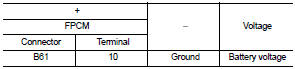
1.CHECK FPCM POWER SUPPLY
1. Turn ignition switch OFF.
2. Disconnect FPCM harness connector.
3. Turn ignition switch ON.
4. Check the voltage between FPCM harness connector and ground.
Is the inspection result normal? YES >> GO TO 2.
NO >> GO TO 3.
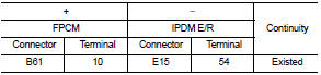
2.CHECK FPCM POWER SUPPLY CIRCUIT
1. Turn ignition switch OFF.
2. Disconnect IPDM E/R harness connector.
3. Check the continuity between FPCM harness connector and IPDM E/R harness connector.
4. Also check harness for short to ground.
Is the inspection result normal? YES >> Perform the trouble diagnosis for power supply circuit.
NO >> Repair or replace error-detected parts.
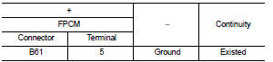
3.CHECK FPCM GROUND CIRCUIT
1. Turn ignition switch OFF.
2. Check the continuity between FPCM harness connector and ground.
3. Also check harness for short to power.
Is the inspection result normal? YES >> GO TO 4.
NO >> Repair or replace error-detected parts.
4.CHECK FPCM INPUT AND OUTPUT CIRCUITS
1. Disconnect ECM harness connector.
2. Check the continuity between FPCM harness connector and ECM harness connector.
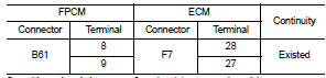
3. Also check harness for short to ground and to power.
Is the inspection result normal? YES >> GO TO 5.
NO >> Repair or replace error-detected parts.
5.CHECK FUEL PUMP CONTROL CIRCUIT
1. Disconnect fuel level sensor unit (fuel pump) harness connector.
2. Check the continuity between FPCM harness connector and fuel level sensor unit (fuel pump) harness connector.
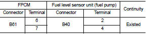
3. Also check harness for short to ground and to power.
Is the inspection result normal? YES >> GO TO 6.
NO >> Repair or replace error-detected parts.
6.CHECK FPCM
Check the FPCM. Refer to EC-325, "Component Inspection (FPCM)".
Is the inspection result normal? YES >> Check intermittent incident .Refer to GI-42, "Intermittent Incident".
NO >> Replace FPCM. Refer to EC-806, "Removal and Installation".
Component Inspection (FPCM)
1.CHECK FUEL PUMP CONTROL MODULE (FPCM)
Check the voltage between FPCM terminals as per the following conditions.
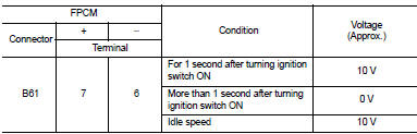
Is the inspection result normal? YES >> INSPECTION END
NO >> Replace FPCM. Refer to EC-806, "Removal and Installation".
 P1217 engine over temperature
DTC Logic
DTC DETECTION LOGIC
NOTE:
• If DTC P1217 is displayed with DTC U1001, first perform the trouble diagnosis
for DTC U1001. Refer
to EC-569, "DTC Logic".
• If DTC P1217 is disp ...
 P1225 TP sensor
DTC Logic
DTC DETECTION LOGIC
DTC CONFIRMATION PROCEDURE
1.PRECONDITIONING
If DTC Confirmation Procedure has been previously conducted, always turn
ignition switch OFF and wait at
least 10 se ...
Other materials:
Manual Transmission (MT)
The ignition switch includes a device that helps prevent accidental removal of
the key while driving.
The key can only be removed when the ignition switch is in the LOCK position.
To turn the ignition switch to the LOCK position from the ACC or ON position,
turn the key to the OFF position, ...
Front wiper does not operate
Description
The front wiper does not operate under any operation conditions.
Diagnosis Procedure
1.CHECK WIPER RELAY OPERATION
CONSULT-III ACTIVE TEST
1. Select “FRONT WIPER” of IPDM E/R active test item.
2. With operating the test item, check front wiper operation.
Lo : Front wiper LO operat ...
Precaution for Supplemental Restraint System (SRS) "AIR BAG" and "SEAT BELT
PRE-TENSIONER"
The Supplemental Restraint System such as “AIR BAG” and “SEAT BELT PRE-TENSIONER”,
used along
with a front seat belt, helps to reduce the risk or severity of injury to the
driver and front passenger for certain
types of collision. Information necessary to service the system safely is
include ...
