Nissan Juke Service and Repair Manual : P1217 engine over temperature
DTC Logic
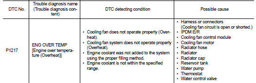
DTC DETECTION LOGIC
NOTE
:
• If DTC P1217 is displayed with DTC UXXXX, first perform the trouble diagnosis
for DTC UXXXX.
• If DTC P1217 is displayed with DTC P0607, first perform the trouble diagnosis for DTC P0607. Refer to EC-304, "DTC Logic".
If the cooling fan or another component in the cooling system malfunctions, engine coolant temperature will rise.
When the engine coolant temperature reaches an abnormally high temperature condition, a malfunction is indicated.
CAUTION:
When a malfunction is indicated, be sure to replace the coolant. Refer to CO-11,
"Draining". Also,
replace the engine oil. Refer to CO-12, "Refilling".
1. Fill radiator with coolant up to specified level with a filling speed of 2 liters per minute. Be sure to use coolant with the proper mixture ratio. Refer to MA-14, "Engine Coolant Mixture Ratio".
2. After refilling coolant, run engine to ensure that no water-flow noise is emitted.
DTC CONFIRMATION PROCEDURE
1.PERFORM COMPONENT FUNCTION CHECK
Perform component function check. Refer to EC-320, "Component Function Check".
NOTE
:
Use component function check to check the overall function of the cooling fan.
During this check, a DTC might
not be confirmed.
Is the inspection result normal? YES >> INSPECTION END
NO >> Proceed to EC-321, "Diagnosis Procedure".
Component Function Check
1.PERFORM COMPONENT FUNCTION CHECK-I
WARNING:
Never remove the radiator cap when the engine is hot. Serious burns could be
caused by high pressure
fluid escaping from the radiator.
Wrap a thick cloth around cap. Carefully remove the cap by turning it a quarter turn to allow built-up pressure to escape. Then turn the cap all the way off.
Check the coolant level in the reservoir tank and radiator.
Allow engine to cool before checking coolant level.
Is the coolant level in the reservoir tank and/or radiator below the proper range? YES >> Proceed to EC-321, "Diagnosis Procedure".
NO >> GO TO 2.
2.PERFORM COMPONENT FUNCTION CHECK-II
Confirm whether customer filled the coolant or not.
Did customer fill the coolant? YES >> Proceed to EC-321, "Diagnosis Procedure".
NO >> GO TO 3.
3.PERFORM COMPONENT FUNCTION CHECK-III
 With CONSULT-III
1. Turn ignition switch ON.
2. Perform “FAN DUTY CONTROL” in “ACTIVE TEST” mode of “ENGINE” using CONSULT-III.
3. Check that cooling fan speed varies according to the percentage.
 Without CONSULT-III
1. Activate IPDM E/R auto active test and check cooling fan motors operation. Refer to PCS-12, "Diagnosis Description".
2. Check that cooling fan operates.
Is the inspection result normal? YES >> INSPECTION END
NO >> Proceed to EC-321, "Diagnosis Procedure".
Diagnosis Procedure
1.CHECK COOLING FAN OPERATION
 With CONSULT-III
1. Turn ignition switch ON.
2. Perform “FAN DUTY CONTROL” in “ACTIVE TEST” mode of “ENGINE” using CONSULT-III.
3. Check that cooling fan speed varies according to the percentage.
 Without CONSULT-III
1. Activate IPDM E/R auto active test and check cooling fan motors operation. Refer to PCS-12, "Diagnosis Description".
2. Check that cooling fan operates.
Is the inspection result normal? YES >> GO TO 2.
NO >> Proceed to EC-420, "Diagnosis Procedure".
2.CHECK COOLING SYSTEM FOR LEAK-I
Check cooling system for leak. Refer to CO-11, "Inspection".
Is leakage detected? YES >> GO TO 3.
NO >> GO TO 4.
3.CHECK COOLING SYSTEM FOR LEAK-II
Check the following for leak.
• Hose (Refer to CO-11, "Inspection".) • Radiator (Refer to CO-15, "RADIATOR : Inspection".) • Water pump (Refer to CO-22, "Inspection".)
>> Repair or replace malfunctioning part.
4.CHECK RADIATOR CAP
Check radiator cap. Refer to CO-15, "RADIATOR CAP : Inspection".
Is the inspection result normal? YES >> GO TO 5.
NO >> Replace radiator cap. Refer to CO-17, "Exploded View".
5.CHECK THERMOSTAT
Check thermostat. Refer to CO-25, "Inspection".
Is the inspection result normal? YES >> GO TO 6.
NO >> Replace thermostat. Refer to CO-24, "Removal and Installation".
6.CHECK WATER CONTROL VALVE
Check water control valve. Refer to CO-27, "Inspection".
Is the inspection result normal? YES >> GO TO 7.
NO >> Replace water control valve. Refer to CO-26, "Exploded View".
7.CHECK ENGINE COOLANT TEMPERATURE SENSOR
Refer to EC-201, "Component Inspection".
Is the inspection result normal? YES >> GO TO 8.
NO >> Replace engine coolant temperature sensor. Refer to CO-26, "Exploded View".
8.OVERHEATING CAUSE ANALYSIS
If the cause cannot be isolated, check the CO-9, "Troubleshooting Chart".
>> INSPECTION END
 P1212 TCS communication line
Description
This CAN communication line is used to control the smooth engine operation
during the TCS operation. Pulse
signals are exchanged between ECM and “ABS actuator and electric unit (contro ...
 P1220 fuel pump control module
(FPCM)
P1220 fuel pump control module
(FPCM)
DTC Logic
DTC DETECTION LOGIC
DTC CONFIRMATION PROCEDURE
1.PRECONDITIONING
1. Turn ignition switch OFF and wait at least 10 seconds.
2. Turn ignition switch ON.
3. Turn ignition switch OFF and ...
Other materials:
ECU diagnosis information
ECM
Reference Value
TERMINAL LAYOUT
PHYSICAL VALUES
NOTE:
• ECM is located in the engine room left side near battery.
• When disconnecting ECM harness connector (1), loosen (B) it with
levers as far as they will go as shown in the figure.
2 : ECM
A : Fasten
• Pulse signal is measured by ...
Jump starting
To start your engine with a booster battery, the instructions and precautions
below must be followed.
WARNING
• If done incorrectly, jump starting can lead to a battery explosion, resulting
in severe injury or death.
It could also damage your vehicle.
• Explosive hydrogen gas is always prese ...
Speed limiter main switch
Component Function Check
1.CHECK SPEED LIMITER MAIN SWITCH FUNCTION
With CONSULT-III
1. Turn ignition switch ON.
2. Select “ENGINE” using CONSULT-III.
3. Select “SL MAIN SW” in “DATA MONITOR” mode.
4. Check “SL MAIN SW” indication under the following condition.
Without CONSULT-III
1. Turn ...
