Nissan Juke Service and Repair Manual : P1205 exhaust fuel injector
DTC Logic
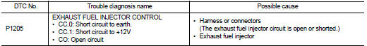
DTC DETECTION LOGIC
Diagnosis Procedure
1.CHECK EXHAUST FUEL INJECTOR POWER SUPPLY CIRCUIT FOR OPEN AND SHORT
1. Turn ignition switch OFF.
2. Disconnect exhaust fuel injector harness connector.
3. Turn ignition switch ON.
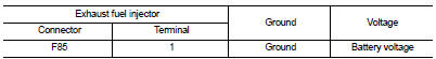
4. Check the voltage between exhaust fuel injector harness connector and ground.
Is the inspection result normal? YES >> GO TO 3.
NO >> GO TO 2.
2.DETECT MALFUNCTIONING PART
Check the following.
• Harness connectors E8, F1 • Harness for open or short between IPDM E/R and exhaust fuel injector
>> Repair open circuit or short to ground or short to power in harness or connectors.
3.CHECK FUEL INJECTOR OUTPUT SIGNAL CIRCUIT FOR OPEN AND SHORT
1. Turn ignition switch OFF.
2. Disconnect ECM harness connector.
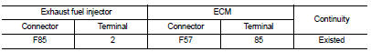
3. Check the continuity between exhaust fuel injector harness connector and ECM harness connector.
4. Also check harness for short to ground and short to power.
Is the inspection result normal? YES >> GO TO 4.
NO >> Repair open circuit or short to ground or short to power in harness or connectors.
4.CHECK EXHAUST FUEL INJECTOR
Refer to EC-983, "Component Inspection".
Is the inspection result normal? YES >> GO TO 5.
NO >> Replace exhaust fuel injector.
5.CHECK INTERMITTENT INCIDENT
Refer to GI-42, "Intermittent Incident", ???INCIDENT SIMULATION TESTS??? and ???GROUND INSPECTION???.
>> INSPECTION END
Component Inspection
1.CHECK EXHAUST FUEL INJECTOR
1. Turn ignition switch OFF.
2. Disconnect exhaust fuel injector harness connector.
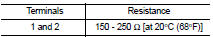
3. Check resistance between exhaust fuel injector terminals as follows.
Is the inspection result normal? YES >> INSPECTION END
NO >> Replace exhaust fuel injector.
 P0833 CPP switch
DTC Logic
DTC DETECTION LOGIC
Diagnosis Procedure
1.CHECK CLUTCH PEDAL POSITION SWITCH GROUND CIRCUIT FOR OPEN AND SHORT
1. Turn ignition switch OFF.
2. Disconnect clutch pedal position switch ...
 P1525 communication circuit for ASCD and speed limiter
DTC Logic
DTC DETECTION LOGIC
...
Other materials:
Back door lock
Exploded View
1. Back door lock assembly
2. TORX bolt
3. Back door striker
: Do not reuse
: N·m (kg-m, ft-lb)
: Body grease
Door lock
DOOR LOCK : Removal and Installation
REMOVAL
1. Remove the back door lower finisher. Refer to INT-35, "BACK DOOR LOWER
FINISHER : Removal and
In ...
Removal and installation
PUSH-BUTTON IGNITION SWITCH
Removal and Installation
REMOVAL
1. Remove the NATS antenna amp. Refer to SEC-167, "Removal and
Installation".
2. Remove the push-button ignition switch.
1. Disengage the push-button ignition switch fixing pawls
using minus driver etc.
2. Press the pu ...
P range interlock door lock/unlock function does not operate
Diagnosis Procedure
1.CHECK “AUTOMATIC LOCK/UNLOCK SELECT” SETTING IN “WORK SUPPORT”
1. Select “DOOR LOCK” of “BCM” using CONSULT-III.
2. Select “AUTOMATIC LOCK/UNLOCK SELECT” in “WORK SUPPORT” mode.
3. Check “AUTOMATIC LOCK/UNLOCK SELECT” in “WORK SUPPORT”.
Refer to DLK-41, "DOOR LOCK : ...
